Instruction manual 91/104 V9.2
Commissioning
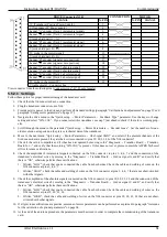
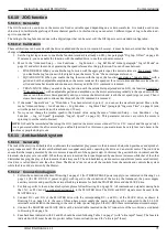
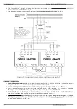
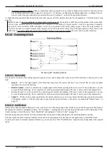
DRIVE (Connector X14)
CONNECTION
MOTOR
SIGNAL
N. PIN
N. PIN
SIGNAL
+5V (Transducer Positive Power Supply)
1
0V (Transducer 0V Power supply)
2
Channel “A" encoder (Track 1 incremental signal)
3
Channel "A“ encoder (Track 1 incremental signal)
4
0V (sock shield pair A + A)
5
Channel “B" encoder (Track 2 incremental signal)
6
Channel "B“ encoder (Track 2 incremental signal)
7
0V (sock shield pair B + B)
8
PTC probe in the motor (signal)
13
──────────
0V (sock shield pair R + R)
16
Channel “R" encoder (signal at zero position)
17
Channel "R“ encoder (signal at zero position)
18
Channel “C" encoder (Track 1 absolute signal)
19
Channel "C“ encoder (Track 1 absolute signal)
20
Channel “D" encoder (Track 2 absolute signal)
21
Channel "D“ encoder (Track 2 absolute signal)
22
PTC probe in the motor (0V)
25
──────────
0V (cable shield) – Connector box
View connector from the soldering side (Connector type “D " 25 pole female).
5.5.2.1 Settings
Follow these points for proper commissioning of the transducer card:
1. Check that the X4 connector has no connection.
2. Plug the transducer connector onto X14.
3. Provide service power to the drive and perform all standard settings (paragraph "Calibration and adjustments“on page 57 and
paragraph "Setting motor parameters“on page 57).
4. Navigate the drive menu to the “Quick setup → Motor Parameters → Feedback Type" parameter. Use the keys to change
setting and select “SIN-COS ". If you cannot select this transducer, see step 7 just ahead to check if the card is working prop -
erly.
5. Scroll through the menu to the parameter “Quick setup → Motor Parameters → Encoder Lines ". Set the number of sinus -
oids/revolution as reported on the plate or technical data of the transducer.
6. Move to the next menu "Quick setup → Motor Parameters → Abs Signal C&D?" and select if the absolute channels of the
SinCos encoder are present: they are the 4 wires connected to pins 19, 20, 21, 22 of the X14 connector?
7. Check if the card is compatible and if it has been recognised by moving to the “Diagnostic → Transduc. Board → Transduc.
Board for...." and verify that the wording "SIN-COS" is present. If this does not occur, please contact the ALTER Technical
Office for some verifications.
8. Check the amplitude of incremental signals connected on the X14 connector to pins 3, 4, 6, 7 and the connection of the
transducer’s electrical wires by moving to the “Diagnostic → Transduc Board → SinCos signal A and B" and verify that
there is "OK", otherwise perform these verifications:
1. Written “LOW”: check that you've connected the cable from both sides. Check the cable and welding of wires on the
X14 connector at pins 3, 4, 6, 7.
2. Written “HIGH”: check the cable and welding of wires on the X14 connector at pins 3, 4, 6, 7 that are not short-circuited
with other signals.
9. Check the amplitude of the absolute signals connected on the X14 connector to pins 19, 20, 21, 22 and the connection of the
transducer’s electrical wires by moving to the “Diagnostic → Transduc Board → SinCos signal C and D" and verify that
there is "OK", otherwise perform these verifications:
1. Written “LOW”: check that you've connected the cable from both sides. Check the cable and welding of wires on the
X14 connector at pins 19, 20, 21, 22.
2. Written “HIGH”: check the cable and welding of wires on the X14 connector at pins 19, 20, 21, 22 that are not short-
circuited with other signals.
10. If all previous verifications are positive, autotune of motor parameters can be performed as explained in paragraph ”Autotune
for the calculation of optional parameters“ on page 58.
11. At the end of the autotune procedure, the parameters must be stored in order to complete the commissioning of the transducer
card.
Alter Elettronica s.r.l.
61

