Instruction manual 91/104 V9.2
Commissioning
•
FAULT: serial communication problem with the encoder. Check the status of the wires and connections on X14 pin 9-10-11-
12, the shielding of the cable, the presence of noise sources near of the cable.
•
OK: The signal from the transducer is correct.
Internal alarm status
Indicates the state of the internal alarms of the EnDat encoder connected to X14. The available statuses are:
•
FAULT: the encoder reports an internal failure. Replace the encoder with a working one.
•
OK: the encoder has no faults.
Compatible encoder
Whether the EnDat encoder connected to X14 is compatible with the 01/327 card. The available statuses are:
•
NO: the encoder isn't compatible. Check the 5.5.4 page paragraph 63 with the list of compatible encoders.
•
YES: the encoder is compatible.
Advanced Setup
Menu group for advanced configurations. Normally these parameters do not serve for normal use of the drive and the variation of
these can cause adjustment instability or make the motor speed control characteristics worse. Before changing the parameters of this
menu group it is necessary to know the product in depth or contact the ALTER technical office for advice and possible clarifications.
Alter Menu
Password protected menu for internal use. It is not recommended to try to access this menu because the modification of these para
-
meters can cause internal damage of the drive with consequent need of repair.
Speed Ramp
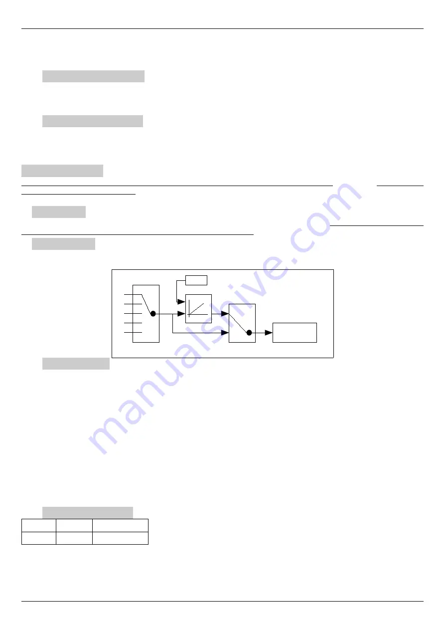
Menu group for adjusting the parameters of the speed ramp that can be inserted with the external command "REN" (see paragraph
"Connector X12“on page 19). In the following drawing you can see how the ramp block is structured.
Ramp Source
Parameter that allows you to select the source of the ramp and then the origin of the speed reference. Using the keys you can select the
source from among these:
•
NOT USED
: the speed reference is always fixed at zero.
•
ANALOG INPUT 1
: the speed reference is taken from the analog input 1. The parameter “Value " relative to this analog in -
put becomes the source of the ramp block.
•
DIGITAL REFER
: the speed reference is a digital value that can be set manually for testing or calibrating the motor. This
reference can also be digitally provided by a communication network (CAN BUS or other). To manually change this value,
see paragraph "Digital Refer.“ just below.
•
SumBlock Summ1
: The speed reference is taken from the “Summ1 " output of the summing block (see paragraph 5.6.14 on
page 75).
•
SumBlock Summ2
: The speed reference is taken from the “Summ2 " output of the summing block (see paragraph 5.6.14 on
page 75).
•
SumBlock Summ3
: The speed reference is taken from the “Summ3 " output of the summing block (see paragraph 5.6.14 on
page 75).
Speed Ramp Time
Minimum Maximum Units of measure
0.1
650.0
Sec
Parameter to set the up/down time of the speed ramp. Assuming an input of 0 to 100 % of the value is given, this parameter is defined
as the time it takes (“Speed Demand ") to go from 0 % to 100 %.
Therefore if the input step goes from 0 % to 50 % it will mean that the time taken to finish the ramp will be half the time set on this
parameter.
Alter Elettronica s.r.l.
47
Drawing 19: Speed ramp
Speed
Demand
Source selector
RAMPA
TIME
TRUE
FALSE
REN


