Instruction manual 91/104 V9.2
Diagnostics
6.2.6 DO3 (Digital Output 3)
Display of digital output status 3. The lighting of this led means that on the corresponding digital output there is the 24V. The function
of this output depends on the programming performed, but in standard configuration indicates that the load on the motor is greater
than 90 %.
6.2.7 DO4 (Digital Output 4)
Display of digital output status 4. The lighting of this led means that on the corresponding digital output there is the 24V. The function
of this output depends on the programming performed, but in standard configuration indicates that the motor has reached the
requested
position.
6.3 Red LEDs – Alarms
6.3.1 FLT (Fault)
Signal that the drive is on alarm. On the LCD display you can read the cause of the alarm in order to eliminate it.
6.4 Alarm messages
•
When the drive goes to alarm, the red FLT LED flashes and the DOK output goes to 0V.
•
The cause of the alarm is clearly written on the LCD display.
•
All alarms are stored if the drive is enabled (DEN command = ON).
•
If the drive is disabled, alarms cease when the cause that generated them is no longer present.
•
The recovery is done with the RST command (see section Connector X12 on page 19) or by pressing one of the buttons on
the front.
•
In case of alarm, the drive will automatically disable and no longer control the motor (motor free).
6.4.1 ADCB not ready
If this alarm appears, turn off the drive and notify the ALTER technical service.
6.4.2 ADC for AI1 fault
If this alarm appears, it means that the A/D drive relative to the analog input 1 has problems. You can try to remove the service
voltage and after a few minutes restore it and see if the message disappears. Otherwise, notify the ALTER Technical Service.
6.4.3 Anti backlash data error
This alarm only appears with the anti-backlash function activated (see section ”Anti-backlash system“ from page 71). The causes of
the alarm are:
•
Incorrect setting of the ”AntiBack Mode“ parameter (see page 49) on the master and/or slave drive.
•
The master and/or slave drive does not update the data exchanged on the bus or is switched off or faulted.
•
There are communication errors on the bus that connects the master drive to the slave drive (X7 connector).
Operations to be carried out:
•
The parameter ”AntiBack Mode“ (see page 49) must be set “MASTER” in the drive that controls the master motor and set
“SLAVE” in the drive that controls the slave motor.
•
Check that both the master drive and the slave drive that there is the illuminated display, that the writings are present and that
by pressing the buttons on the front you can navigate the menu.
•
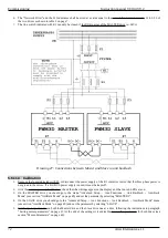
Check that the twisted double connecting the X7 connectors of the two drives is connected as shown in 25 on page 68. In the
presence of severe disturbances it is advisable to use a shielded cable with the two ends of the screen connected to the drive
case.
•
If the alarm only appears when the motor is running, you can try to disable the control of communication errors on the bus
using the menu ”Net Errors“ on page 50.
6.4.4 Anti backlash slave fault
This alarm only appears with the anti-backlash function activated (see section ”Anti-backlash system“ from page 71) on the master
drive display and indicates that the slave drive have an alarm. If you look at the front of the slave drive you should see the green LED
DOK off and possibly an alarm message or a signal on its lcd display. The cause of this alarm should be sought in the slave drive and
not in the master drive.
Alter Elettronica s.r.l.
77

