


Rockwell Automation Publication 1791ES-UM001G-EN-P - November 2016
91
Configure the I/O Modules
Chapter 5
2. From the Port Mode pull-down menus, select the desired configuration
option for each point.
Configure the Module
Outputs
provides information for configuring the test outputs.
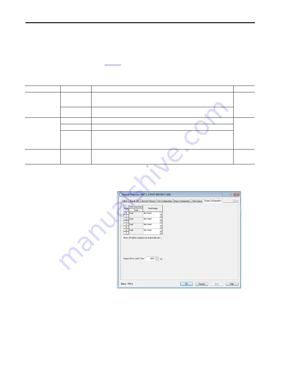
Follow these steps to configure the module outputs.
1. For Point Operation, select single or dual.
.
2. For Point Mode, select Not Used, Safety, or Safety Pulse Test. See the
Safety Output Parameters table for additional information.
3. Select a value for Output Error Latch Time. Output Error Latch Time is
the time that the module holds an error to make sure that the controller
can detect it. This setting provides you more reliable diagnostics and
enhances the changes that a nuisance error is detected.
4. Click Apply from the bottom of the dialog box.
Table 25 - Guidelines for Configuring Safety Outputs
Parameter Name
Value
Description
Default
Point Operation Type
Dual
The 1791ES modules, the 1732ES-IB12XOBV2 module, and the 1732ES-IB8XOBV4 module treat the outputs as
a pair. It always sets them HI to LO as a matched pair. Safety logic must set both of these outputs ON or OFF
simultaneously or the module declares a channel fault.
Dual-channel
Single
The 1732ES-IB12XOB4 module can be configured with the outputs treated as single channels. Both channels of
an output pair are set to either Single or Dual.
Point Mode
Not Used
The output is disabled.
Not Used
Safety
The output point is enabled, and it does not perform a pulse test on the output.
Safety Pulse Test
The output point is enabled and performs a pulse test on the output.
When the output is energized, the output pulses LO briefly. The pulse test detects if 24V remains on the output
terminal during this LO pulse due to a short to 24V. The pulse test also detects if the output is shorted to
another output terminal.
Output Error Latch Time
0…65,530 ms (in
increments of 10 ms)
The purpose for latching output errors is to make sure that intermittent faults that can only exist for a few
milliseconds are latched long enough for the controller to read. The amount of time to latch the errors is based
on the RPI, the safety task watchdog, and other application-specific variables.
1000 ms
Содержание 1732ES-IB12XOB4
Страница 6: ...6 Rockwell Automation Publication 1791ES UM001G EN P November 2016 Table of Contents Notes ...
Страница 8: ...8 Rockwell Automation Publication 1791ES UM001G EN P November 2016 Summary of Changes Notes ...
Страница 38: ...38 Rockwell Automation Publication 1791ES UM001G EN P November 2016 Chapter 2 About the Modules Notes ...
Страница 174: ...174 Rockwell Automation Publication 1791ES UM001G EN P November 2016 Index Notes ...
Страница 175: ......