background image

Page 24

aERO MODEL TyPE

In the default configuration, the Model Select List contains 5 AERO Model Types and 5 HELI Model Types. The Model Type 

for any of the 10 models in the Model Select List can be changed using the TYPE menu. For more Information, see page 25.

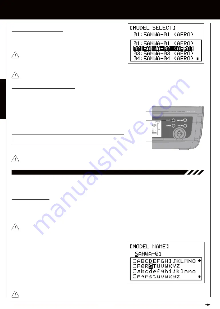
Using the Direct Model Select Function

The Direct Model Select function allows you to select one of first three models from memory without going through the MODEL 

SELECT menu. This makes it much quicker and easier to load the Programming Data for your three most-used models.

Before flying, verify that the Model Name displayed at the top of the Display screen is the actual model that you'll be flying.

1)  Turn the transmitter OFF.

2)  Press and HOLD the programming key of the model you wish to setup 

or fly, then turn the transmitter ON. The Model Name will be displayed 

at the top of the Display screen.

INC+/M1  selects  Model  1,  DEC-/M2  selects  Model  2,  and  END/M3 

selects Model 3.

Model 1

Model 2

Model 3

02.MODEL naME (MODEL naMing)

The Model Naming function allows you to name each of the 10 individual models. This makes it easy to keep track of multiple 

models. The Model Name can consist of up to 8 letters, numbers, or symbols. Choose from capital letters, lower case letters, 

numbers, and various symbols.

Entering a Model Name

1)  From the Display screen, press the ENTER key to display the Programming Menus.

2)  Press the Navigation Pad 

56

 to highlight MODEL NAME, then press the ENTER key to display the MODEL NAME menu. 

The cursor will default to the left side of the top row of letters and an underscore will appear under the first character in the name.

A model must be selected before a Model Name can be entered or modified. In the default configuration, M01:SANWA-1 

is selected. To enter a Model Name for another model, that model must first be selected using the MODEL SELECT menu 

or the Direct Model Select function. For more information, see the 01.MODEL SELECT section on page 23.

When you press the ENTER key to select a model, the Programming 

Data for that model will be loaded immediately.

Selecting a Model, Continued....

3)  Press the Navigation Pad 

56

 to highlight the model you would like to 

select, then press the ENTER key to select the highlighted model. That 

model will be displayed above the Model Select List.

3)  Press the Navigation Pad 

5634

 to highlight a character, then press 

the ENTER key to select the highlighted character. That character will be 

displayed and the underscore will move to the next space.

4)  Repeat step 3 to enter the rest of the characters. Up to eight characters 

can be entered. The name of your model will be displayed on the 

top of the Display screen.

Press the Navigation Pad 

56

 repeatedly to scroll up and down the list of characters. In addition, press the INC+/M1 and 

DEC-/M2 keys to move the underscore left and right respectively.

Содержание SD-6G

Страница 1: ...Page 1...

Страница 2: ...tions Page 6 Features Familiarization Page 7 Transmitter Features Diagrams Page 7 Receiver Features Diagram Page 8 Features Descriptions Page 8 Servo Connections Page 9 Transmitter Alarms Page 9 Servo...

Страница 3: ...Statement The SD 6G transmitter has been tested and meets the FCC RF exposure guidelines when used with the Airtronics accessories supplied or designated for this product and provided at least 20cm s...

Страница 4: ...expose the transmitter to excessive heat moisture fuel exhaust residue etc l Do not expose the transmitter to excessive heat or direct sunlight Leaving the transmitter in direct sunlight can damage th...

Страница 5: ...manufacturer disclaims all responsibility for damages resulting from use of components other than genuine Airtronics components It is extremely important to install the receiver and route the receiver...

Страница 6: ...xing l V Tail Mixing with End Point Adjustment l Delta Elevon Mixing with End Point Adjustment l 2 Programmable Compensation Mixers l Common or Flight Mode Specific Trim with Throttle Trim Lock helico...

Страница 7: ...point the antenna directly at your aircraft as this results in a weakened signal For more information see page 4 Antenna Power Indicator Power Switch Charging Jack Aileron Elevator Control Stick Throt...

Страница 8: ...hile still providing long usage time and high power output Bind Button Used to Bind the transmitter and receiver Also used to enter Low Power Range Check mode Bind LED Displays the current status of t...

Страница 9: ...you should not fly The RF Output Indicator will flash when the transmitter Trainer mode is set to Slave features descriptions Continued The 92224 RX600 6 Channel receiver included with your SD 6G 2 4...

Страница 10: ...x 1 61in 39 1 x 20 0 x 40 9mm Weight 2 36oz 67gr Torque 42oz in 3 0kg cm 4 8v 53oz in 3 8kg cm 6 0v Speed 0 20 sec 60 4 8v 0 16 sec 60 6 0v Dimensions 1 54 x 0 79 x 1 42in 39 1 x 20 0 x 36 0mm Weight...

Страница 11: ...ption make sure that the CCPM swashplate type matches your model exactly l After making your selections press the ENTER key then the INC M1 key The pre programmed model template will be loaded into th...

Страница 12: ...to load the programming for your three favorite models l Pressing both the INC M1 and DEC M2 keys together will Reset the highlighted programming selection to the Factory Default Setting l When the D...

Страница 13: ...switch harness and or the receiver See plug polarity diagram above l Observe all safety precautions provided with your battery before use during use and during the charging process WARNING The nominal...

Страница 14: ...quire an 8 hour charge 1200 150 8 l Always follow the charging procedures described below to ensure the safe and correct use of the rechargeable batteries and charger l Before charging the batteries d...

Страница 15: ...el Select function F MODE Flight Mode Select Cycles through the three Flight Modes during programming Does NOT switch between Flight Modes during use INC M1 Increase Model 1 DEC M2 Decrease Model 2 IN...

Страница 16: ...el Number Displays the Number of the currently selected Model Model Type Icon Displays the current Active Model Type loaded into memory either AERO Aircraft icon or HELI Helicopter icon Rudder Trim Di...

Страница 17: ...plete fail safe programming The Fail Safe function automatically sets the servos to a predetermined position in the event that the signal between the transmitter and the receiver is interrupted whethe...

Страница 18: ...wires with force Do not cut or extend the receiver antenna wires l The coaxial cables the thicker portion of the receiver antenna wires can be bent into gentle curves however do not bend the coaxial...

Страница 19: ...ge Checking 1 Turn the receiver in your aircraft ON 2 With the transmitter in Low Power Mode Bind LED flashing walk approximately 30 paces from your aircraft approximately 90 feet and with the help of...

Страница 20: ...ht Mode to FN using the Flight Mode Switches move both Flight Mode switches forward The LCD will read normally the Flight Mode Warning alarm will cease and RF Output Indicator will stop flashing There...

Страница 21: ...30 CENTER Servo Centering Sub Trim Page 31 EPA End Point Adjustment Page 32 TH CUT Throttle Cut Page 33 D R EXP Dual Rate and Exponential Page 34 TRIM Digital Trim Page 36 TH CURVE Throttle Curve Pag...

Страница 22: ...l to the desired Programming Menu Press the ENTER key to access the desired Programming Menu From within any Programming Menu press the END M3 key continuously to return to the Display screen Unless o...

Страница 23: ...Flight Mode F1 Throttle Cut Flight Mode F2 Landing Gear 01 Model SelE Model Select The Model Select function allows you to load the Programming Data for the particular model you wish to fly The MODEL...

Страница 24: ...press the ENTER key to display the Programming Menus 2 Press the Navigation Pad 56 to highlight MODEL NAME then press the ENTER key to display the MODEL NAME menu The cursor will default to the left...

Страница 25: ...ghlight TYPE then press the ENTER key to display the TYPE menu The cursor will default to AERO or HELI depending on the particular model you ve selected 3 If the current Model Type is HELI press the I...

Страница 26: ...d control of the model returns instantly to the Instructor Making AERO Model Type Selection Options Continued 2 Press the Navigation Pad 56 to highlight the AERO Model Type selection option you wish t...

Страница 27: ...in the model you re using for training and verify that the Instructor s transmitter controls the model s control surfaces correctly 3 Activate the Trainer function by pulling and HOLDING the Trainer s...

Страница 28: ...nd 1 10 Seconds 00 Minutes 00 Seconds 00 1 10 Seconds Using the Stop Watch 1 Press the END M3 key two times to return to the Display screen The Start time that you programmed will be displayed Using t...

Страница 29: ...o flash in the Programming Window It s not possible to copy Programming Data from one model to the same model If you attempt this ENTER will not be displayed 5 Press the ENTER key DATA COPY OK will be...

Страница 30: ...ill continue to flash in the Programming Window 4 Press the ENTER key DATA RESET OK will be displayed and INC will flash 5 Press the INC M1 key to Reset the Programming Data for the selected model Aft...

Страница 31: ...l 5 will be displayed as RA Right Aileron Centering the Trim Switches and Servo Horns 1 Before changing the Servo Centering percentage values you must first adjust each of the four trim switches so th...

Страница 32: ...nsure the End Points haven t changed In the default configuration the same trim settings are stored across all Flight Modes This option can be changed to allow you to store different trim settings for...

Страница 33: ...the center of the servo arm or move the pushrod further away from the control surface 11 th cut throttle cut The Throttle Cut function allows you to set a specific position that the throttle servo wi...

Страница 34: ...Programming F MODE Transmitter F MODE refers to the Flight Mode that the transmitter is currently operating in Programming F MODE refers to the Flight Mode that you would like to change the programmi...

Страница 35: ...he Dual Rate 1 percentage value to no more than 100 This will prevent any chance of exceeding your End Point Adjustment and overdriving your control linkage Choosing the Channel 1 Press the Navigation...

Страница 36: ...ue for either 1 or 2 3 Press the INC M1 or DEC M2 keys to set the desired Exponential percentage value for the channel you chose previously EXP setting range is 100 to 100 The default setting is 0 Lin...

Страница 37: ...trol stick is at half the engine is not at half power In addition many times the difference between three quarter power and full power is almost indistinguishable Using the Throttle Curve function you...

Страница 38: ...tage values unless specifically necessary for your particular setup This will prevent any chance of overdriving your control linkage 1 Press the Navigation Pad 6 to highlight POINT 1 2 Press the INC M...

Страница 39: ...rential function your aircraft must feature two separate aileron servos and you must choose the AILE 2 Model Type selection option in the TYPE menu Choosing the Flight Mode Common or Separate 1 From t...

Страница 40: ...ing aileron roll control Both ailerons can also be programmed to move up at the same time spoilerons to rapidly decrease lift On some aircraft moving both ailerons up slightly can induce greater speed...

Страница 41: ...vel will increase in the opposite direction 1 Press the Navigation Pad 6 to highlight FL4LA 0 then press the INC M1 or DEC M2 keys to change the Flaperon4Left Aileron Mixing percentage value 2 Press t...

Страница 42: ...ravel This mix is Linear 1 Press the Navigation Pad 6 to highlight FL4EL 0 then press the INC M1 or DEC M2 keys to change the Flap4Elevator Mixing percentage value 18 dual el dual elevator Mixing end...

Страница 43: ...ion for Choose from FN F1 or F2 Changing Dual Elevator Mixing End Point Adjustment Percentage Values Both the Up and Down and the Right and Left elevator percentage values can be changed separately Pr...

Страница 44: ...menu In addition depending on the specific orientation of your elevator control linkages in order for the Ailvator Mixing function to work as intended one of the elevator servos may need to be revers...

Страница 45: ...il Mixing function to work as intended one of the servos may need to be reversed using the NOR REV setting in the REVERSE menu so that both control surfaces move Up and Down together using the elevato...

Страница 46: ...to equalize control deflection and in addition allows you the ability to change the control deflection amount of each servo in both directions This allows greater flexibility in making control surfac...

Страница 47: ...The default setting is 80 Decreasing the Delta Mixing End Point Adjustment percentage value will decrease the movement for that specific servo and direction of travel Increasing the Delta Mixing End...

Страница 48: ...he Flight Mode Common or Separate 1 From the Display screen press the ENTER key to display the Programming Menus 2 Press the Navigation Pad 56 to highlight either C MIX1 or C MIX2 then press the ENTER...

Страница 49: ...Slave channel servo travels and the amount that it travels relative to the Master channel servo The Rate High and Rate Low percentage values are a ratio of Slave channel servo travel to Master channe...

Страница 50: ...d the Slave channel is the Flap channel The RATE Hi and RATE Lo percentage values define how far Up and Down the both ailerons will move together and is a percentage of the FL4LA and FL4RA percentage...

Страница 51: ...SET Model Programming Data Reset Page 60 REVERSE Servo Reversing Page 61 CENTER Servo Centering Sub Trim Page 61 EPA End Point Adjustment Page 63 CP EPA CCPM End Point Adjustment Page 64 SWASH Swashpl...

Страница 52: ...e desired Programming Menu general information From within any Programming Menu press the END M3 key continuously to return to the Display screen If the Display screen is not displayed when you turn t...

Страница 53: ...ainer Flight Mode F1 Throttle Cut Flight Mode F2 Not Used When any switch is moved into the Up or Forward position pushed away from you this is considered the OFF position When moved into the Down or...

Страница 54: ...model naming The Model Naming function allows you to name each of the 10 individual models This makes it easy to keep track of multiple models The Model Name can consist of up to 8 letters numbers or...

Страница 55: ...t to HELI or AERO depending on the particular model you ve selected 3 If the current Model Type is AERO press the INC M1 or DEC M2 keys to change the selection option to HELI Changing the Model Type 1...

Страница 56: ...ment of those servos 120 90 and 1 1 refers to the physical relationship and geometry of the servo placements on the swashplate NORMAL Non CCPM CP3F 120 with 3 Servos CP3B 120 with 3 Servos CP3L 120 wi...

Страница 57: ...needs to be turned ON using the DISPLAY key l Both transmitters must be programmed identically for the Trainer System to function properly For example Servo Reversing End Point Adjustments etc must b...

Страница 58: ...in an allotted amount of time to ensure that your model doesn t run out of fuel Setting the Stop Watch 1 From the Display screen press the ENTER key to display the Programming Menus 2 Press the Naviga...

Страница 59: ...ress the DEC M2 key a second time To Reset the Stop Watch to the programmed Start time press the INC M1 and DEC M2 keys at the same time 05 Stop Watch Stop watch and count up timer continued 06 data c...

Страница 60: ...et to the factory default settings by pressing the INC M1 and DEC M2 keys at the same time however this is time consuming if you want to change all of the selected model s programming settings back to...

Страница 61: ...he Navigation Pad 56 to highlight REVERSE then press the ENTER key to display the REVERSE menu The cursor will default to 1EL NOR 3 Press the Navigation Pad 5634 to highlight the channel that you woul...

Страница 62: ...to change the Servo Centering percentage value for 4 Press the INC M1 or DEC M2 keys to change the Servo Centering percentage value to center the servo horn 5 Repeat steps 3 and 4 to center the servo...

Страница 63: ...End Point Adjustment percentage value for Down elevator push the elevator control stick forward then release it D will be displayed in front of the Elevator End Point Adjustment percentage value 3 Pr...

Страница 64: ...ases servo travel and decreasing the CCPM End Point Adjustment percentage value decreases servo travel 5 Repeat steps 3 and 4 to change the CCPM End Point Adjustment percentage values for the desired...

Страница 65: ...press the ENTER key to display the Programming Menus 2 Press the Navigation Pad 56 to highlight SWASH then press the ENTER key to display the SWASH menu The cursor will default to 1 and the adjustmen...

Страница 66: ...ity 13 th cut throttle cut Continued Changing the Throttle Cut Percentage Value 1 From the Display screen press the ENTER key to display the Programming Menus 2 Press the Navigation Pad 56 to highligh...

Страница 67: ...be set for EL Elevator AI Aileron and RU Rudder 2 Press the Navigation Pad 56 to highlight D R EXP then press the ENTER key to display the D R EXP menu The cursor will default to D R 100 3 Press the...

Страница 68: ...setting range is 100 to 100 The default setting is 0 Linear Increasing the Exponential percentage value softens the control feel around neutral Decreasing the Exponential percentage value heightens th...

Страница 69: ...light Mode you re using when you change the trim using the trim switches For example you could have 10 clicks of Up elevator trim in Flight Mode FN Normal and 5 clicks of Up elevator trim in Flight Mo...

Страница 70: ...ill flash WARNING Keep in mind that it s possible to set the Rate percentage values higher or lower than the throttle End Point Adjustment percentage values For example with the throttle High End Poin...

Страница 71: ...rcentage value set to 150 the servo will move 150 when the Throttle Hold is Activated We strongly recommend that you set the Throttle Hold Rate percentage value no higher than your throttle End Point...

Страница 72: ...isualization Transmitter F MODE refers to the Flight Mode that the transmitter is currently operating in Programming F MODE refers to the Flight Mode that you would like to change the programming for...

Страница 73: ...urve and Point 5 is at the high end of the Pitch Curve Point 3 is a the center of the Pitch Curve In the default configuration the Pitch Curve is Linear For example when you move the throttle control...

Страница 74: ...or Programming F MODE Transmitter F MODE IMPORTANT We DO NOT recommend using the Revolution Mixing function with a Heading Hold mode or AVCS mode gyro The Revolution Mixing function should only be use...

Страница 75: ...Hold mode gain and Rate mode gain remotely Two separate Remote Gyro Gain Control function settings can be programmed and one can be selected at any time using the two position Gyro switch For example...

Страница 76: ...rogram your gyro in either Heading Hold mode or Rate mode will be determined by the NOR REV settings of the gyro channel in the REVERSE menu For example if the gyro channel is set to NOR Normal in the...

Страница 77: ...mposed of a Master channel and a Slave channel Any of the available six channels can be programmed as a Master or a Slave The same channel can even be programmed as both a Master and a Slave In additi...

Страница 78: ...channel For example if you set the Master channel to EL Elevator and the Slave channel to AI Aileron when you move the elevator control stick the aileron servo will move 1 Press the Navigation Pad 6...

Страница 79: ...to reduce the tendency of the helicopter to slightly rise and fall as you pirouette For example when you command a pirouette to the left the helicopter will rise slightly and will require you to redu...

Страница 80: ...th servo movements when you apply different mixing values The Servo Monitor also indicates which channel slots in the receiver to plug your servos into 1 EL 2AI 3TH 4RU 5GY and 6FL Using the Servo Mon...

Страница 81: ...ction Servo horn s not centered Control linkage s bind RF Output Indicator flashes Transmitter Bind LED flashes Transmitter Bind LED goes out Reinstall batteries Observe correct polarity Contact Airtr...

Страница 82: ...the signal from the transmitter to the receiver in the model The Antenna should be pivoted into the vertical position during use When not in use the Antenna should be collapsed into the horizontal po...

Страница 83: ...ws you to vary the amount of servo travel in relation to the movement of the elevator aileron and rudder control sticks near the neutral positions to change the way the control surfaces react to contr...

Страница 84: ...Model 2 key the END M3 End Model 3 key and the F MODE Flight Mode key RF Output Indicator Illuminates when the transmitter is turned ON and transmitting a signal If the RF Output Indicator fails to il...

Страница 85: ...time the Instructor feels that the Student is in a situation that endangers the model the Instructor releases the Trainer Switch and control of the model returns instantly to the Instructor Trim Swit...

Страница 86: ...Length 19 Count Up Timer Using Aero Model Type 28 Count Up Timer Using Heli Model Type 59 Current Drain Transmitter Specification 6 D Data Copy Using Aero Model Type 29 Data Copy Using Heli Model Type...

Страница 87: ...Model Type Programming Menu Flow Chart 52 I Inhibit Definition of 83 Input Voltage Receiver Specification 6 INC M1 Key Overview 15 L Landing Gear Switch Definition of 83 Landing Gear Switch Diagram o...

Страница 88: ...ction Charger Warning Using with Transmitter 14 Pitch Curve Definition of 84 Pitch Curve Programming Heli Model Type 72 Power Indicator Definition of 9 84 Power Indicator Diagram of 7 Power Supply Tra...

Страница 89: ...ottle Cut Programming Heli Model Type 51 Throttle Hold Definition of 85 Throttle Hold Activating and Programming Heli Model Type 71 Throttle Trim Lock Programming Aero Model Type 37 Throttle Trim Lock...

Страница 90: ...TS AERO SETUP SHEET Use this Aero Setup Sheet to help you keep track of each of your model s Programming Data Before filling out this Setup Sheet for the first time make several copies of it to use wi...

Страница 91: ...P SHEETS heli SETUP SHEET Use this Heli Setup Sheet to help you keep track of each of your model s Programming Data Before filling out this Setup Sheet for the first time make several copies of it to...

Страница 92: ...service airtronics net http globalservices globalhobby com http www airtronics net Features and Specifications are Subject to Change Without Notice All contents 2010 Airtronics Inc All Rights Reserve...

Отзывы: