background image

Remote GPIB Interface 

Serial BERT 12.5 Gb/s User Guide 


83 


5.6


Examples 


The following programming example assumes the user is programming with 

Agilent BASIC, a simple interpretative language that is convenient for 

instrument programming.  
 
For the example programs below, the device being programmed is located at 

GPIB device address 725. The actual address varies according to how you have 

configured the GPIB bus for your own application. For information to change 

the bus address see Section 5. 
 
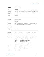
This first block of code shows how to initialize the instrument and check the 

GPIB subsystem for errors. 


10 OUTPUT 725; "*IDN?"           ! request the instrument ID string  
20 ENTER  725; result$           ! read the return string  
30 PRINT result$          

   ! print the results to stdout  

30 OUTPUT 725; ":SYSTEM:ERROR?"  ! check for errors 
40 OUTPUT 725; "*RST" 

         ! reset the BERT 


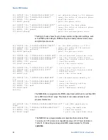
The next block of code shows how to save the instrument state in one of the 

save/recall registers (0-9), how to change the value of the internal HF clock, 

and how to restore the previous instrument state saved in the save/recall 

register. 


50 OUTPUT 725; "*SAV 1"                 ! save current inst. state in reg 1 
60 OUTPUT 725; ":SOURCE:ROSC:FREQ 11111"! change the BERT freq to 11111MHz 
70 OUTPUT 725; ":SOURCE:ROSC:INT:FREQ?" ! query the source frequency  
80 ENTER  725; freq$ 

                ! read the result 

90 PRINT freq$                          ! print the frequency results   
100 OUTPUT 725; "*RCL 1" 

          ! recall the prior state (frequency) 


The next block of code shows how to get the SCPI version number. 


110 OUTPUT 725; ":SYSTEM:VERSION?"  ! query the control version 
120 ENTER  725; version$            ! read the result 
130 PRINT version$                  ! print the version   


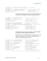
This block shows how to manually set the error detector phase, and how to 

use the automatic detector phase adjust feature via GPIB control. 


Содержание N4962A

Страница 1: ...Agilent N4962A Serial BERT 12 5 Gb s User Guide...

Страница 2: ...written agreement with warranty terms covering the material in this document that conflict with these terms the warranty terms in the separate agreement shall control Technology Licenses The hardware...

Страница 3: ...nt Conditions This instrument is intended for indoor use in an installation category II pollution degree 2 environment per IEC 61010 Second Edition and 664 respectively It is designed to operate withi...

Страница 4: ...mity with the relevant European Directives EMC Directive 2004 108 EC and Low Voltage Directive 2006 95 EC China RoHS regulations include requirements related to packaging and require compliance to Chi...

Страница 5: ...ectronic product in domestic household waste Product category With reference to the equipment types in the WEEE Directive Annexure I this product is classed as a Monitoring and Control instrumentation...

Страница 6: ......

Страница 7: ...ons 14 1 4 Connect the Hardware 14 1 5 Turn It On 15 1 6 Align Clock and Data 15 1 7 Make the Measurement 15 2 N4962A System Overview 17 2 1 Front Panel Quick Reference 19 2 2 Rear Panel Quick Referen...

Страница 8: ...Self Test Mode 54 4 5 2 Error Free Test 55 4 5 3 High BER Test 55 4 5 4 Low BER Test 56 4 6 BER Detector Clock Phase Adjustment 56 4 7 Basic BER Measurement 59 5 Remote GPIB Interface 61 5 1 GPIB Capa...

Страница 9: ...amplitude control Electronic receiver clock phase adjust Differential inputs and outputs Synchronous clock pattern triggers Selectable pattern lengths mark density Data Thru switch on Receiver for us...

Страница 10: ...stment Operating modes Disabled safe mode no output Enabled PRBS output enabled Thru no detector inputs connected to Data Thru connectors on back panel Display LED indicators Multifunction alphanumeri...

Страница 11: ...and R D lab use The N4962A features high UI jitter injection and programmable output amplitude Figure 1 Eye waveform The N4962A generates a continuous bit pattern that is applied to the DUT then fed...

Страница 12: ...his product must be used in a normal condition in which all means for protection are intact only Before switching on this instrument make sure the supply voltage is in the specified range This instrum...

Страница 13: ...case parts Do not attempt to clean internally The Mains wiring and connectors shall be compatible with the connector used in the premise electrical system Failure to ensure adequate earth grounding by...

Страница 14: ...savers or adaptors Keep cable lengths short and minimize number of cable bends Use a 7 10 in lbs torque wrench when attaching connectors Terminate all unused RF connectors with 50 terminations 1 4 Con...

Страница 15: ...PRBS button only if the DUT is inverting o When on the PRBS will generate an inverted output signal Press the Display Scroll button and select Press the Adjust Config State button to auto set the det...

Страница 16: ...Getting Started 16 Serial BERT 12 5 Gb s User Guide...

Страница 17: ...r injection PRBS generator TX with variable output amplitude control Error detector RX with electronic clock phase adjustment The N4962A is controlled by front panel buttons and remote GPIB IEEE 488 2...

Страница 18: ...tinuous bit stream triggered by the input clock rate configured by the selectable pattern length mark space density data inversion and error injection settings The output is amplified by a programmabl...

Страница 19: ...Connectors RECEIVER IN IN SMA input to error detector differential or single ended SOURCE OUT OUT 2 92 mm K PRBS generator output differential or single ended Display display panel eight character dis...

Страница 20: ...l 2 buttons adjust the PRBS output amplitude up or down shown on display 2 buttons adjust the detector clock phase up or down shown on display Config State 2 buttons change value of the currently disp...

Страница 21: ...ck off 1 Internal clock on Err00000 Lowest digits of error counter ErAd OFF PRBS digital error injection OFF 1E0 1E1 1E7 errors per second NoData 0 Error detector data sense 0 data sense off 1 data se...

Страница 22: ...rigO SMA high frequency 9 85 11 35 GHz clock output LF TrigO SMA low frequency 616 709 MHz clock output Ext CKI SMA low frequency 616 709 MHz clock input used to phase lock with external clock source...

Страница 23: ...l shall only be done with the instruments power cord removed and in a well ventilated area Allow all residual alcohol moisture to evaporate and the fumes to dissipate prior to energizing the instrumen...

Страница 24: ...N4962A System Overview 24 Serial BERT 12 5 Gb s User Guide...

Страница 25: ...t be terminated with the included 50 terminated connectors 3 1 General Table 2 General and mechanical parameters of N4962A Operating Temperature 10 C to 40 C Storage Temperature 40 C to 70 C Power Req...

Страница 26: ...om mains before cleaning Use a dry cloth or one slightly dampened with water to clean the external case parts Do not attempt to clean internally For continued protection against fire hazard replace fu...

Страница 27: ...12 5 GHz clock is required to trigger the PRBS generator and error detector The generator and detector operate at 1 bit per clock cycle 10 Gb s at a clock speed of 10 GHz Figure 5 N4962A block diagra...

Страница 28: ...ondition should 1 Turn on the internal synthesizer synth to 1 2 Turn off the external signal generator RF output 3 Set the external signal generator to the new 1 16th rate frequency 4 Set the N4962A t...

Страница 29: ...and at least 4 dBm 1 V pp is applied to the RXCKI input Do not apply more than 10 dBm 2 V pp to these inputs Table 4 Parameters for N4962A internal clock TX CKO RX CKO HF TrigO Frequency 9 85 to 11 3...

Страница 30: ...ates a continuous bit stream based on the configuration settings and the TX CKI input clock rate The internal clock can be used for 9 85 to 11 35 Gb s operation or an external clock can be used for 50...

Страница 31: ...ers for N4962A PRBS generator OUT OUT Data rate 0 5 to 12 5 Gb s PRBS patterns 2n 1 n 7 10 15 23 31 Mark space density 1 2 1 4 1 8 Pattern invert available for all patterns Error injection selectable...

Страница 32: ...s to 12 5 Gb s operation The PRBS generator and error detector must be clocked at the same rate The error detector samples the input bit stream on the rising edge of the clock If the clock transition...

Страница 33: ...y from 5 Gb s to 12 5 Gb s The linearity accuracy of phase is limited to 10 degree steps for operation from 5 Gb s to 12 5 Gb s For external clock rates below 5 GHz the specific values of 0 90 180 or...

Страница 34: ...Path The N4962A can operate in one of three data path configurations The data path can be set from the front panel detailed in Section 4 2 2 or through GPIB remote commands The current data path is i...

Страница 35: ...35 Table 10 N4962A data path configurations Data Path light Configuration PRBS generator Additional path loss Disabled IN IN connected to error detector default Disabled Enabled IN IN connected to err...

Страница 36: ...System Details and Performance Specifications 36 Serial BERT 12 5 Gb s User Guide...

Страница 37: ...e ESD protection at all times but especially when handling RF input outputs ground coaxial cable conductor pins before use to remove static buildup Situate the instrument away from heat sources Do not...

Страница 38: ...with 50 terminations 4 1 2 Connector Care The N4962A serial BERT 12 5 Gb s features high quality SMA connectors and two 2 92 mm K connectors for the front panel OUT OUT interface Agilent Technologies...

Страница 39: ...URCE are 2 92 mm K connectors The PRBS output is available in single ended or differential form from these connectors The output signal is specified in Section 3 3 The error detector connectors labele...

Страница 40: ...for a short period of time when the error detector identifies a bit error If the error light is solid red many errors are being detected N A display panel The eight character display shows the curren...

Страница 41: ...62A front panel local receiver and data path controls Table 12 N4962A front panel local receiver and data path controls Text Type Description Default Local button light Light indicates local control O...

Страница 42: ...r Puts detector into training mode for auto synchronization of incoming bit stream If detector is OFF pressing button Resets state bits errors seconds Turns on detector OFF Data Path PRBS Invert butto...

Страница 43: ...to error detector PRBS generator is disabled Enabled IN IN connected to error detector PRBS generator is enabled Thru IN IN connected to DataThru DataThru with some path loss PRBS generator is enabled...

Страница 44: ...just Ampl UP and DOWN buttons Buttons adjust PRBS output amplitude by 10 mV UP increases amplitude max 1800 mV DOWN decreases amplitude min 300 mV Display will briefly show new amplitude setting after...

Страница 45: ...ion This setting is for optionally applying the DC 100 MHz jitter input signal When 1 the modulator bandwidth is increased to allow the jitter input to be FM modulated onto the clock signals The jitte...

Страница 46: ...State PLUS button will prompt the N4962A to automatically determine the optimum detector clock phase This is detailed further in Section 4 6 NoData 0 o options 0 1 NoData option helps with the initial...

Страница 47: ...gree phase point This option allows the user to specify the measurement depth of the autophase algorithm APT allows a tradeoff between the search time and positioning accuracy of the autophase algorit...

Страница 48: ...added errors per second Expected BER 10 GHz clock no other errors Expected BER 12 5 GHz clock no other errors OFF 0 0 1E0 1E 10 8E 11 1E1 1E 9 8E 10 1E2 1E 8 8E 9 1E3 1E 7 8E 8 1E4 1E 6 8E 7 1E5 1E 5...

Страница 49: ...ER defined as the total number of bit errors divided by the total number of bits bit counters detailed in Table 9 If the error detector is on Receiver On light is ON the BER shown is a measurement tha...

Страница 50: ...ressing the Adjust Config State PLUS button will prompt the N4962A to automatically determine the optimum detector clock phase This is detailed in Section 4 6 Config State Displays one of ten configur...

Страница 51: ...erator is enabled and is available from the OUT OUT connectors when this data path is selected The input signal is not processed by the error detector and errors are not counted The Pat TrigO connecto...

Страница 52: ...nal clock system with a LF external signal The Ext CKI port is detailed in Section 3 3 JitterI is a DC 100 MHz input that is FM modulated onto the TX CKO and HF TrigO clock A sinusoid should be applie...

Страница 53: ...e Setting Display Description Value Local Light Local push button vs GPIB control On Receiver On Light Error detector Off PRBS Light PRBS output inverted Off Data Path 3 lights Data path Disabled Erro...

Страница 54: ...nal clock at the default setting power the system turn on the PRBS output and adjust the error detector clock phase as follows Connect TX CKO to TX CKI with coaxial cable included default Connect RX C...

Страница 55: ...elect time sec should be increasing 4 5 3 High BER Test To verify that the error detector can correctly count a large number of errors first allow the detector to synchronize with a clear input signal...

Страница 56: ...Press the Display Scroll button and select Err should show 1 per second Press the Display Scroll button and select BER should show 1E 10 Press the Display Scroll button and select time sec should be i...

Страница 57: ...r clock phase for the best sampling point It requires that the system settings and data path allow error free operation This is best achieved by putting the system into self test mode described in Sec...

Страница 58: ...t be on Ensure the Receiver On is not selected the error detector must be off Press the Display Scroll button and select Find the optimal sampling point as follows If the Error light is off press the...

Страница 59: ...le Connect DUT output to IN with short 50 coax cable Optionally connect DUT output to IN with short phase balanced 50 coax cable Add appropriate attenuation or gain to DUT output output signals Termin...

Страница 60: ...Operation 60 Serial BERT 12 5 Gb s User Guide...

Страница 61: ...itute of Electrical and Electronic Engineers IEEE Standard 488 2 1987 IEEE Stand Codes Formats Protocols and Communication Commands for Use with ANSI IEEE Std 488 1 1987 New York NY 1987 A GPIB interf...

Страница 62: ...ndshake capability T6 Basic talker serial poll unaddressed to talk if addressed to listen no talk only L4 Basic listener unaddressed to listen if addressed to talk no listen only SR1 Complete service...

Страница 63: ...rface using commands and queries The commands and queries are documented in the Backus Naur Form notation detailed in Table 18 Table 18 N4962A GPIB command and query syntax Symbol Meaning Defined elem...

Страница 64: ...the message into segments for the instrument to process Link a command sub function Not all commands have links Argument a quantity quality restriction or limit associated with the header or link Com...

Страница 65: ...able 19 N4962A IEEE common commands Command Function CLS Clear status command RST Reset command WAI Wait to continue TRG Trigger IDN Identification Query STB Status Byte Query TST Self Test Query ESR...

Страница 66: ...summarized in Table 21 The following descriptions and examples assume the user is programming with Agilent BASIC a simple interpretative language that is convenient for instrument programming For the...

Страница 67: ...NSe APTime 1 value 5000 SENSe ROSCillator PHASe AUTO 0 value 360 SENSe SWEep TIME 0 001 value 4194303 999 SENSe TRAIn 10 value 6500 STATus OPERation MEASurement CONDition INITiate BER TRIGger INITiate...

Страница 68: ...5 SOUR ROSC SOUR ENTER 725 value PRINT value should be INT Command SOURce ROSCillator INTernal FREQuency Type Query Description Returns the current value of the programmable high frequency clock in MH...

Страница 69: ...OURce ROSCillator JITTer ON OFF Type Command Description Sets the jitter injection mode If 1 the high jitter mode will be enabled and the jitter input signal JitterI will be FM modulated onto the TX C...

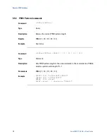
Страница 70: ...n length Results PRBS 7 10 15 23 31 Example See below Command SOURce PATTern PRBS 7 10 15 23 31 Type Command Description Sets PRBS pattern length to the value indicated in the command line PRBSn selec...

Страница 71: ...space MS 2 4 8 Type Command Description Sets PRBS pattern mark space density to the value indicated in the command line MSn selects a pattern with mark space density of 1 n Parameters MS 2 4 8 Example...

Страница 72: ...725 value PRINT value should be ON Command SOURce PRBS IERR RATe Type Query Description Returns the current error injection rate Results OFF ERR1E 0 value 7 Example See below Command SOURce PRBS IERR...

Страница 73: ...de in mVpp per side double this number for differential Results 300 value 1800 Example See below Command SOURce VOLTage AMPLitude 300 value 1800 Type Command Description Sets the single ended PRBS out...

Страница 74: ...OFF Type Command Description Sets the instrument data path NORMal Normal operation IN IN connected to error detector PRBS generator enabled THRU Input through IN IN connected to DataThru DataThru PRB...

Страница 75: ...the data sense option Results ON OFF Example See below Command SENSe NOData ON OFF Type Command Description Sets the NoData sense function When used with the N4962A source helps to detect all zeros d...

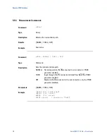
Страница 76: ...f the NoData flag determined by the instrument only if NODATA is turned on see above the query returns 0 when the NoData condition is met NORXCLK Indicates the current status of the NoRXClk flag the q...

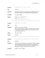
Страница 77: ...rns the error detector clock phase Phase is selected in 2 degree increments for data rates greater then 5 GHz to 12 5 GHz Data rates between 500 MHz and less than 5 GHz offer values of 0 90 180 270 de...

Страница 78: ...un for in seconds Results 0 001 value 4194303 999 Example See below Command SENSe SWEep TIME 0 001 value 4194303 999 Type Command Description Sets the desired measurement time in seconds The lowest nu...

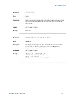
Страница 79: ...ore the measurement starts in 1 10ths of a microsecond Results 10 value 6500 Example See below Command SENSe TRAIn 10 value 6500 Type Command Description Sets the desired training delay time in 1 10th...

Страница 80: ...WE TIME 10 OUTPUT 725 TRIG INIT WAIT 2 OUTPUT 725 STAT OPER MEAS COND ENTER 725 value PRINT value should be 1 Command INITiate BER Type Command Description Latches data on BERT board equivalent to tur...

Страница 81: ...ied by other commands Parameters Example See below Command SENSe DATA BCOunt ECOunt ETIMe BER ALL Type Querry Description Returns the selected parameter from the current instrument sample or returns a...

Страница 82: ...nning This command can only be used if the set up measurement time from the command SENSe SWEep TIME value is completed See examples 470 580 BCOunt Total number of bits counted ECOunt Total number of...

Страница 83: ...SYSTEM ERROR check for errors 40 OUTPUT 725 RST reset the BERT The next block of code shows how to save the instrument state in one of the save recall registers 0 9 how to change the value of the int...

Страница 84: ...source 270 OUTPUT 725 SOURCE ROSC SOURCE query the current source setting 280 ENTER 725 source read the result 290 PRINT source print the source value 300 OUTPUT 725 SOURCE ROSC JITT ON turn jitter i...

Страница 85: ...540 ENTER 725 result read the result 550 PRINT result print the query result 560 OUTPUT 725 FETCH BER query BER statistics 570 ENTER 725 result read the result 580 PRINT result print the query result...

Страница 86: ...Remote GPIB Interface 86 Serial BERT 12 5 Gb s User Guide...

Страница 87: ...2 5 Gb s fails system verification and you cannot correct the problem return it to Agilent Technologies for repair following the steps shown below 1 Record all symptoms 2 Contact Agilent Technologies...

Страница 88: ...Copyright Agilent Technologies 2012 Third edition May 2013 Printed in Germany...

Отзывы: