


System Details and Performance Specifications
Serial BERT 12.5 Gb/s User Guide
29
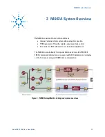
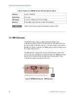
The LF clock is multiplied up to HF clock frequencies and is split into two
output paths: a transmit clock for the PRBS generator, TX CKO, which can be
modulated with an external jitter input signal, and a receive clock for the error
detector, RX CKO. Both outputs are buffered. The clock outputs are connected
by default to the input clock connectors for the PRBS generator and error
detector, TX CKI and RX CKI, with a pair of coaxial cable loops.
To trigger the PRBS generator and error detector with an external 500 MHz to
12.5 GHz clock, remove the coax loops and apply the external source to TX CKI
and RX CKI. The generator and detector must be triggered with the same
phase-synchronous clock. Ensure that at least 0 dBm (630 mV pp) is applied to
the TXCKI input and at least +4 dBm (1 V pp) is applied to the RXCKI input. Do
not apply more than +10 dBm (2 V pp) to these inputs.
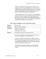
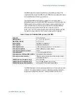
Table 4. Parameters for N4962A internal clock (TX CKO, RX CKO, HF TrigO)
Frequency
9.85 to 11.35 GHz
Resolution
10 MHz front-panel, 1 MHz GPIB
Output power
TX CKO, Typ: +4 dBm (1 V pp)
RX CKO, Typ: +4 dBm (1 V pp)
HF TrigO, Typ: +6 dBm (1.3 V pp)
Connector
Female SMA, single-
ended, AC coupled, 50 Ω impedance
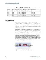
The TX clock, available from the buffered HF TrigO and TX CKO connectors,
features the optional addition of an external jitter signal.
To add jitter to the PRBS clock, and therefore to the PRBS output signal,
switch into jitter-injection mode by changing the Config State “Jitter” setting
to 1, and apply a DC to 100 MHz sinusoid to the JitterI connector. The jitter
input signal will be FM modulated onto the clock; the amount of added jitter
corresponds to the amplitude of the input signal.
The Jitter setting of 0 will still FM modulate any signal under 100 kHz. To
properly ensure no jitter is added, disconnect any source from the JitterI
connector.
Содержание N4962A
Страница 1: ...Agilent N4962A Serial BERT 12 5 Gb s User Guide...
Страница 6: ......
Страница 16: ...Getting Started 16 Serial BERT 12 5 Gb s User Guide...
Страница 24: ...N4962A System Overview 24 Serial BERT 12 5 Gb s User Guide...
Страница 36: ...System Details and Performance Specifications 36 Serial BERT 12 5 Gb s User Guide...
Страница 60: ...Operation 60 Serial BERT 12 5 Gb s User Guide...
Страница 86: ...Remote GPIB Interface 86 Serial BERT 12 5 Gb s User Guide...
Страница 88: ...Copyright Agilent Technologies 2012 Third edition May 2013 Printed in Germany...


