System Details and Performance Specifications
30
Serial BERT 12.5 Gb/s User Guide
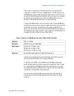
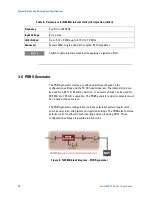
Table 5. Parameters for N4962A internal clock jitter injection (JitterI)
Frequency
Typ: DC to 100 MHz
Input Voltage
2 V pp max
Jitter Added
Up to 5 UI ≤ 2 M
Hz, up to 0.
15 UI ≥
10 MHz
Connector
Female SMA, single-
ended, DC coupled, 50 Ω impedance
Switch to jitter-injection mode before applying a signal to JitterI
3.4
PRBS Generator
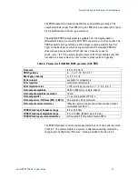
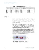
The PRBS generator creates a continuous bit stream based on the
configuration settings and the TX CKI input clock rate. The internal clock can
be used for 9.85 to 11.35 Gb/s operation, or an external clock can be used for
500 Mb/s to 12.5 Gb/s operation. The PRBS generator and error detector must
be clocked at the same rate.
The PRBS generator configuration includes selectable pattern length, mark
space density ratio, and digital error injection settings. The PRBS also features
polarity control to allow for both inverting and non-inverting DUTs. These
configuration settings are detailed in Section 4.2.
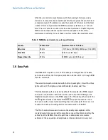
Figure 6. N4962A block diagram – PRBS generator
Содержание N4962A
Страница 1: ...Agilent N4962A Serial BERT 12 5 Gb s User Guide...
Страница 6: ......
Страница 16: ...Getting Started 16 Serial BERT 12 5 Gb s User Guide...
Страница 24: ...N4962A System Overview 24 Serial BERT 12 5 Gb s User Guide...
Страница 36: ...System Details and Performance Specifications 36 Serial BERT 12 5 Gb s User Guide...
Страница 60: ...Operation 60 Serial BERT 12 5 Gb s User Guide...
Страница 86: ...Remote GPIB Interface 86 Serial BERT 12 5 Gb s User Guide...
Страница 88: ...Copyright Agilent Technologies 2012 Third edition May 2013 Printed in Germany...


