99
Troubleshooting and Test Functions
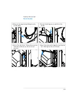
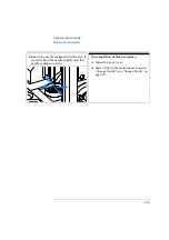
Poor alignment, seen during vial pickup and vial replacement and/or when the
needle hits the gripper arm
Poor alignment, seen during vial pickup
and vial replacement and/or when the
needle hits the gripper arm
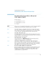
With Error messages
❏
motor overtemp (0 or 2 or 3)
❏
movement failed (0 or 2 or 3)
N O T E
When a motor over temperature message has occurred, the sampler must be
turned off for about 10 minutes to allow the motor to cool down.
Step 1
Check the firmware and update to the latest revision if necessary.
Since revision A.03.61 (resident A03.60) most of following “movement failed”,
“motor over temp” and “initialization failed (X-axis)” errors are solved.
Step 2
Reset the sampler alignment to default value.
Reset tray alignment, and transport alignment is possible with the Control
Module and the Chemstation. To reset the transport alignment with the
Chemstation enter following command in the command line.
Print sendmodule$(lals, “tray:alig 0.00,0.00”)
Step 3
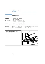
Lubricate the X-gear.
Friction can result in the belt slipping on the gear so that the position of the
belt teeth towards the gear changes.To avoid this, apply some grease from
the sample transport repair kit to the
X-motor-gear.
N O T E
Do not use other grease as the one in the kit and carefully follow the
instruction from the technical note.
Содержание G1313A
Страница 1: ...s1 Agilent 1100 Series Standard Micro and Preparative Autosamplers Reference Manual ...
Страница 3: ...Reference Manual Agilent 1100 Series Standard Micro and Preparative Autosamplers ...
Страница 12: ...12 Contents ...
Страница 39: ...2 2 Optimizing Performance How to optimize the autosamplers to achieve best results ...
Страница 49: ...3 3 Troubleshooting and Test Functions The modules built in troubleshooting and test functions ...
Страница 93: ...93 Troubleshooting and Test Functions Step Commands ...
Страница 159: ...5 5 Parts and Materials Detailed illustrations and lists for identification of parts and materials ...
Страница 160: ...160 Parts and Materials Main Assemblies Main Assemblies Figure 19 Autosampler Main Assemblies 5 3 4 2 1 9 8 7 6 ...
Страница 166: ...166 Parts and Materials Analytical Head Assembly Figure 21 Analytical Head Assembly 2 3 4 5 6 1 ...
Страница 191: ...191 Parts and Materials Remote Cables NOTE START and STOP are connected via diodes to pin 3 of the 3394 connector ...
Страница 216: ...216 Introduction to the Autosampler Electrical Connections ...
Страница 217: ...7 7 Theory of Operation Theory of operation of mechanical hardware electronics and instrument interfaces ...
Страница 244: ...244 Theory of Operation The Main Power Supply Assembly ...
Страница 265: ...265 Introduction to the Control Module Diagnostics and Tests ...
Страница 268: ...268 Introduction to the Control Module Diagnostics and Tests ...
Страница 269: ...9 9 Specifications Performance specifications of the Agilent 1100 Series Standard Micro and Preparative Autosamplers ...
Страница 274: ...274 Specifications Performance Specifications ...
Страница 275: ...10 Legal Safety and Warranty Information ...
Страница 286: ...286 Agilent Technologies on Internet ...
Страница 290: ...290 Index ...
Страница 291: ......

