214
Introduction to the Autosampler
Electrical Connections
Electrical Connections
WA R N I N G
Never use cables other than the ones supplied by Agilent Technologies
to ensure proper functionality and compliance with safety or EMC
regulations.
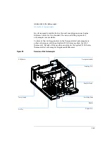
Figure 37
Autosampler Electrical Connections
•
The GPIB connector is used to connect the autosamplers with a
computer. The address and control switch module next to the GPIB
connector determines the GPIB address of your autosamplers. The
switches are preset to a default address (see Table 50 on page 232)
which is recognized once after power on.
•
The CAN bus is a serial bus with high-speed data transfer. The two
connectors for the CAN bus are used for internal Agilent 1100 Series
module data transfer and synchronization.
•
The REMOTE connector may be used in combination with other
analytical instruments from Agilent Technologies if you want to use
features such as common shut down, prepare, and so on.
•
The RS-232 connector may be used to control the autosamplers from a
computer through an RS-232 connection, using appropriate software.
GPIB
RS232C
CAN-bus
Remote
Vial number output
Relay contacts
Содержание G1313A
Страница 1: ...s1 Agilent 1100 Series Standard Micro and Preparative Autosamplers Reference Manual ...
Страница 3: ...Reference Manual Agilent 1100 Series Standard Micro and Preparative Autosamplers ...
Страница 12: ...12 Contents ...
Страница 39: ...2 2 Optimizing Performance How to optimize the autosamplers to achieve best results ...
Страница 49: ...3 3 Troubleshooting and Test Functions The modules built in troubleshooting and test functions ...
Страница 93: ...93 Troubleshooting and Test Functions Step Commands ...
Страница 159: ...5 5 Parts and Materials Detailed illustrations and lists for identification of parts and materials ...
Страница 160: ...160 Parts and Materials Main Assemblies Main Assemblies Figure 19 Autosampler Main Assemblies 5 3 4 2 1 9 8 7 6 ...
Страница 166: ...166 Parts and Materials Analytical Head Assembly Figure 21 Analytical Head Assembly 2 3 4 5 6 1 ...
Страница 191: ...191 Parts and Materials Remote Cables NOTE START and STOP are connected via diodes to pin 3 of the 3394 connector ...
Страница 216: ...216 Introduction to the Autosampler Electrical Connections ...
Страница 217: ...7 7 Theory of Operation Theory of operation of mechanical hardware electronics and instrument interfaces ...
Страница 244: ...244 Theory of Operation The Main Power Supply Assembly ...
Страница 265: ...265 Introduction to the Control Module Diagnostics and Tests ...
Страница 268: ...268 Introduction to the Control Module Diagnostics and Tests ...
Страница 269: ...9 9 Specifications Performance specifications of the Agilent 1100 Series Standard Micro and Preparative Autosamplers ...
Страница 274: ...274 Specifications Performance Specifications ...
Страница 275: ...10 Legal Safety and Warranty Information ...
Страница 286: ...286 Agilent Technologies on Internet ...
Страница 290: ...290 Index ...
Страница 291: ......


