238
Theory of Operation
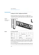
Setting the 8-bit Configuration Switch
Communication Settings for RS-232C Communication
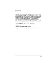
The communication protocol used in this instrument supports only
hardware handshake (CTS/RTS).
Switches 1 in down and 2 in up position define that the RS-232C
parameters will be changed. Once the change has been completed, the
instrument must be powered up again in order to store the values in the
non-volatile memory.
Use the following tables for selecting the setting which you want to use for
RS-232C communication. The number 0 means that the switch is down and
1 means that the switch is up.
One start bit and one stop bit are always used (not selectable).
Table 55
Communication Settings for RS-232C Communication
Mode Select
1
2
3
4
5
6
7
8
RS-232C0
1
Baud rate
Data
Bits
Parity
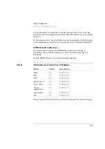
Table 56
Baud Rate Settings
Switches
Baud Rate
Switches
Baud Rate
3
4
5
3
4
5
0
0
0
9600
1
0
0
9600
0
0
1
1200
1
0
1
14400
0
1
0
2400
1
1
0
19200
0
1
1
4800
1
1
1
38400
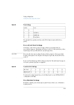
Table 57
Data Bit Settings
Switch 6
Data Word Size
0
7 Bit Communication
1
8 Bit Communication
Содержание G1313A
Страница 1: ...s1 Agilent 1100 Series Standard Micro and Preparative Autosamplers Reference Manual ...
Страница 3: ...Reference Manual Agilent 1100 Series Standard Micro and Preparative Autosamplers ...
Страница 12: ...12 Contents ...
Страница 39: ...2 2 Optimizing Performance How to optimize the autosamplers to achieve best results ...
Страница 49: ...3 3 Troubleshooting and Test Functions The modules built in troubleshooting and test functions ...
Страница 93: ...93 Troubleshooting and Test Functions Step Commands ...
Страница 159: ...5 5 Parts and Materials Detailed illustrations and lists for identification of parts and materials ...
Страница 160: ...160 Parts and Materials Main Assemblies Main Assemblies Figure 19 Autosampler Main Assemblies 5 3 4 2 1 9 8 7 6 ...
Страница 166: ...166 Parts and Materials Analytical Head Assembly Figure 21 Analytical Head Assembly 2 3 4 5 6 1 ...
Страница 191: ...191 Parts and Materials Remote Cables NOTE START and STOP are connected via diodes to pin 3 of the 3394 connector ...
Страница 216: ...216 Introduction to the Autosampler Electrical Connections ...
Страница 217: ...7 7 Theory of Operation Theory of operation of mechanical hardware electronics and instrument interfaces ...
Страница 244: ...244 Theory of Operation The Main Power Supply Assembly ...
Страница 265: ...265 Introduction to the Control Module Diagnostics and Tests ...
Страница 268: ...268 Introduction to the Control Module Diagnostics and Tests ...
Страница 269: ...9 9 Specifications Performance specifications of the Agilent 1100 Series Standard Micro and Preparative Autosamplers ...
Страница 274: ...274 Specifications Performance Specifications ...
Страница 275: ...10 Legal Safety and Warranty Information ...
Страница 286: ...286 Agilent Technologies on Internet ...
Страница 290: ...290 Index ...
Страница 291: ......

