3 Installing the BenchBot Robot workstation
About the BenchBot Disable Hub
54
BenchBot Robot Safety and Installation Guide
Figure
Bypass interlock key setting
Connection panel
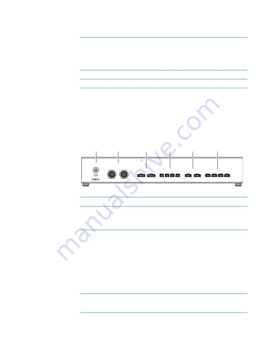
The following diagram and table show the connection panel on the back side of
the BenchBot Disable Hub.
IMPORTANT
Unused emergency- stop and interlock ports must have jumpers
installed.
Figure
BenchBot Disable Hub back view
Key setting
0 = Normal
1 = Bypass
Emergency
stop
0 = Normal
1 = Stopped
Light
Curtain
0 = Normal
1 = Tripped
Door
0 = Closed
1 = Open
BenchBot
Robot
0 = Enabled
1 = Disable
3 = Slow
Device
0 = Enabled
1 = Disabled
1
0
0 or 1
0 or 1
3
1
1
1
0 or 1
0 or 1
1
1
Emergency-Stop Inputs
Interlock Inputs
BenchBot Outputs
Pendant 1 Pendant 2
1
2
4
3
Robot 2
Robot 1
Light Curtain
Power In
24V ,1A
Transmitter
Receiver
Device Outputs
1
2
3
4
1
2
3
4
5
6
Item
Name
Description
1
Power In
Connects the power supply to the
hub. Make sure the power supply is
connected to an AC outlet with a
safety earth grounding pin.
2
Light Curtain
Connects the Light Curtain to the
hub.
•
Transmission
. The gray
transmitter cable connects to
the Transmitter port.
•
Receiver
. The black receiver
cable connects to the Receiver
port.
Note:
If your workstation employs a
shield, use the Interlock Inputs
ports (
4
).
3
Emergency- Stop Inputs
Connects up to two BenchBot
Robot emergency- stop pendants to
the hub.
Содержание BenchBot
Страница 1: ...BenchBot Robot Safety and Installation Guide Original Instructions...
Страница 4: ...Contents iv BenchBot Robot Safety and Installation Guide...
Страница 10: ...Preface Reporting problems x BenchBot Robot Safety and Installation Guide...
Страница 71: ......
Страница 72: ...Safety and Installation Guide G5486 90001 Revision 01 June 2011...


