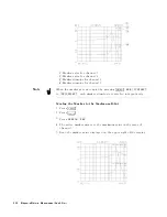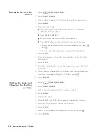
6.
Enter
the
required
value
in
volts
or
amps
,
then
press
4
x1
5 .
(Do
not
use
the
hard
key
for
units
,
4
k/m
5
4
M/
5
4
G/n
5 )
7.
The
stimulus
is
changed
from
one
to
another
measurement
points
that
is
dened
by
the
number
of
points
.
It
takes
few
seconds
per
one
point.
8.
After
the
measurement
is
completed,
the
message
\complete"
is
displayed.
9.
The
measurement
result
is
displayed
on
the
data
trace
and
the
actual
OSC
level
that
was
applied
to
the
DUT
is
displayed
on
the
memory
trace
.
If
the
\over
ow"
message
is
displayed
after
the
measurement
is
nished,
it
means
that
the
analyzer
could
not
regulate
the
OSC
level
to
your
setting
value
at
some
frequency
.
If
you
want
to
read
the
actual
applied
OSC
level,
perform
the
following
procedure
.
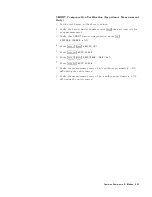
1.
Press
4
Ma
rk
er
5 .
2.
T
oggle
NNNNNNNNNNNNNNNNNNNNNNNNNNNNNNNNNNNNNNNNN
MKR
ON
[DATA]
to
NNNNNNNNNNNNNNNNNNNNNNNNNN
[MEMORY]
.
3.
Move
the
marker
to
your
required
stimulus
position.
4.
Read
the
marker
value
on
the
upper
right
of
screen.
When
you
read
the
value
,
replace
the
displayed
unit
(example
,
F
,
or
H)
with
\V"
for
voltage
setting,
or
\A"
for
current
setting.
Note
While
the
program
is
running,
the
number
of
points
is
set
to
2.
If
you
abort
the
program,
set
the
number
of
points
to
your
required
number
.
A
uto
Level
Control
Measurement
for
OSC
Level
Sweep
The
furnished
sample
program
disk
(Agilent
PN
04291-18000)
includes
the
A
uto
Level
Control
program
(ACI )
for
OSC
level
sweep
.
This
allows
you
to
make
a
measurement
that
the
actual
OSC
level
applied
to
the
DUT
is
equal
to
the
value
you
set.
After
you
set
the
analyzer
to
the
required
setting,
execute
the
program.
The
program
sweeps
the
OSC
level
which
you
set
and
monitor
the
actual
OSC
level
applied
to
the
DUT
,
and
calculate
the
start/stop
value
of
OSC
level,
then
the
result
is
displayed
and
the
program
ends
.
If
the
\over
ow"
message
is
displayed
after
the
measurement
is
nished,
it
means
that
the
analyzer
could
not
regulate
the
OSC
level
to
your
setting
value
.
1.
Insert
the
sample
program
disk
into
the
oppy
disk
drive
.
2.
Press
4
Displa
y
5
NNNNNNNNNNNNNNNNNNNNNNNNNNNNNNNNNNNNNNNNNNNNNNNNNNNNNNNN
DISPLAY
ALLOCATION
NNNNNNNNNNNNNNNNNNNNNNNNNNNNNNNNNNNNNN
BASIC
STATUS
and
type
GET
"ACI"
and
then
press
4
Return
5 .
3.
Press
4
Sw
eep
5
NNNNNNNNNNNNNNNNNNNNNNNNNNNNNNNN
SWEEP
MENU
NNNNNNNNNNNNNNNNNNNNNNNNNNNNN
OSC
LEVEL
.
4.
Set
the
analyzer
to
the
required
setting.
5.
Type
RUN
and
then
press
4
Return
5 .
6-12
Features
Common
to
All
Modes
Содержание 4291B
Страница 20: ......
Страница 24: ...Figure 2 1 Contents 2 4 Installation and Set Up Guide ...
Страница 26: ...Figure 2 2 Agilent Part Numbers of Power Cables 2 6 Installation and Set Up Guide ...
Страница 34: ...Figure 2 7 Connecting a Keyboard 2 14 Installation and Set Up Guide ...
Страница 60: ......
Страница 104: ......
Страница 130: ......
Страница 152: ......
Страница 158: ......

