


Marker
for
a
Cole-Cole
Plot
.
.
.
.
.
.
.
.
.
.
.
.
4-22
10.
Measuring
Other
MUT
s
.
.
.
.
.
.
.
.
.
.
.
.
.
.
4-22
F
or
More
Information
.
.
.
.
.
.
.
.
.
.
.
.
.
.
.
.
.
4-22
5.
Magnetic
Material
Measurement
Quick
Start
Overview
.
.
.
.
.
.
.
.
.
.
.
.
.
.
.
.
.
.
.
.
.
.
5-1
Brief
Measurement
Theory
.
.
.
.
.
.
.
.
.
.
.
.
.
5-2
Basic
Measurement
Flow
.
.
.
.
.
.
.
.
.
.
.
.
.
.
5-3
Required
Equipment
.
.
.
.
.
.
.
.
.
.
.
.
.
.
.
.
5-4
1.
P
ower
ON
.
.
.
.
.
.
.
.
.
.
.
.
.
.
.
.
.
.
.
.
.
5-5
2.
Calibration
.
.
.
.
.
.
.
.
.
.
.
.
.
.
.
.
.
.
.
.
5-5
Calibration
Procedure
.
.
.
.
.
.
.
.
.
.
.
.
.
.
.
.
5-6
3.
Connecting
the
T
est
Fixture
.
.
.
.
.
.
.
.
.
.
.
.
5-9
Selecting
Fixture
and
Holder
.
.
.
.
.
.
.
.
.
.
.
.
5-9
Connecting
the
T
est
Fixture
to
the
T
est
Head
.
.
.
.
.
5-9
Selecting
the
T
est
Fixture
.
.
.
.
.
.
.
.
.
.
.
.
.
.
5-11
4.
Fixture
Compensation
.
.
.
.
.
.
.
.
.
.
.
.
.
.
.
5-11
P
erforming
SHORT
Compensation
.
.
.
.
.
.
.
.
.
.
5-11
SHORT
Compensation
Key
Sequence
.
.
.
.
.
.
.
.
5-12
5.
Input
the
MUT
Size
.
.
.
.
.
.
.
.
.
.
.
.
.
.
.
.
5-12
6.
Placing
the
MUT
on
the
T
est
Fixture
.
.
.
.
.
.
.
.
5-13
7.
Setting
up
the
Analyzer
.
.
.
.
.
.
.
.
.
.
.
.
.
.
5-14
7-1.
Setting
up
for
r
0
-
r
00
vs
.
Frequency
.
.
.
.
.
.
5-15
7-2.
Setting
up
for
r
0
-
r
00
vs
.
OSC
Level
.
.
.
.
.
.
5-16
7-3.
Setting
up
for
r
0
-
r
00
vs
.
Dc-I
(Option
001
only)
5-17
Display
Annotations
.
.
.
.
.
.
.
.
.
.
.
.
.
.
.
.
5-18
8.
Measuring
the
MUT
.
.
.
.
.
.
.
.
.
.
.
.
.
.
.
.
5-19
P
erforming
A
utomatic
Scaling
.
.
.
.
.
.
.
.
.
.
.
.
5-19
9.
Analyzing
a
Measurement
Result
.
.
.
.
.
.
.
.
.
.
5-19
Using
the
Marker
.
.
.
.
.
.
.
.
.
.
.
.
.
.
.
.
.
.
5-19
Reading
a
Measured
V
alue
.
.
.
.
.
.
.
.
.
.
.
.
.
5-19
Moving
the
Marker
to
the
Maximum
P
oint
.
.
.
.
.
5-20
Clearing
the
Marker
.
.
.
.
.
.
.
.
.
.
.
.
.
.
.
5-21
10.
Measuring
Other
MUT
s
.
.
.
.
.
.
.
.
.
.
.
.
.
.
5-21
F
or
More
Information
.
.
.
.
.
.
.
.
.
.
.
.
.
.
.
.
.
5-21
6.
F
eatures
Common
to
All
Modes
P
erforming
User
Dened
Calibration
.
.
.
.
.
.
.
.
.
.
6-2
User
Dened
Calibration
Description
.
.
.
.
.
.
.
.
.
6-2
P
erforming
User
Dened
Fixture
Compensation
.
.
.
.
6-3
User
Dened
Fixture
Compensation
Description
.
.
.
6-3
P
erforming
A
veraging
.
.
.
.
.
.
.
.
.
.
.
.
.
.
.
.
.
6-3
P
erforming
P
oint
A
veraging
.
.
.
.
.
.
.
.
.
.
.
.
.
6-3
P
erforming
Sweep
A
veraging
.
.
.
.
.
.
.
.
.
.
.
.
6-4
A
veraging
Description
.
.
.
.
.
.
.
.
.
.
.
.
.
.
.
6-4
Using
P
oint
Delay
and
Sweep
Delay
.
.
.
.
.
.
.
.
.
.
6-5
Making
a
P
oint
Delay
Measurement
.
.
.
.
.
.
.
.
.
6-5
Making
a
Sweep
Delay
Measurement
.
.
.
.
.
.
.
.
.
6-5
Delay
Description
.
.
.
.
.
.
.
.
.
.
.
.
.
.
.
.
.
.
6-5
Changing
the
Number
of
Measurement
P
oints
.
.
.
.
.
6-6
Number
of
Measurement
P
oints
Description
.
.
.
.
.
6-6
Applying
Dc
Bias
(Option
001
Only)
.
.
.
.
.
.
.
.
.
.
6-6
Monitoring
the
OSC
Level
or
the
Dc
Bias
Level
.
.
.
.
.
6-7
P
erforming
a
GO/NO-GO
T
est
.
.
.
.
.
.
.
.
.
.
.
.
.
6-8
Editing
a
Limit
Line
T
able
.
.
.
.
.
.
.
.
.
.
.
.
.
.
6-8
Contents-3
Содержание 4291B
Страница 20: ......
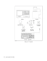
Страница 24: ...Figure 2 1 Contents 2 4 Installation and Set Up Guide ...
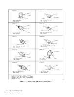
Страница 26: ...Figure 2 2 Agilent Part Numbers of Power Cables 2 6 Installation and Set Up Guide ...
Страница 34: ...Figure 2 7 Connecting a Keyboard 2 14 Installation and Set Up Guide ...
Страница 60: ......
Страница 104: ......
Страница 130: ......
Страница 152: ......
Страница 158: ......


