


Ndrive HL User’s Manual
Technical Details
www.aerotech.com 3-15
3.3.3. Brake Output
The brake output provides a direct connection to the brake the relay on the optional –
IOPSO board. The brake output will be present on this connector only when the –IOPSO
option board is present, allowing the brake signal to utilize the existing feedback cable
without the need for additional wiring. See Section 4.1.3. in Chapter 4, for more
hardware information on the brake output. The brake output may be automatically
controlled via the drive, when activated via the BrakeOnDriveDisable axis parameter, or
manually toggled via the BRAKE command, see the NView help for more information.
See Table 3-12 for the mating connector part number.
Table 3-15.
Brake Output Pin Assignment on ConnectorJ207
Pin #
Label
Description
In/Out/Bi.
13
Brake -
Optional Brake Relay - Output
Output
25
Brake +
Optional Brake Relay + Output
Output
3.3.4. Encoder Interface
The three encoder signals consists of the following: sine (Sin), cosine (Cos), and marker
(Mkr) as well as their complimentary signals: sine-n (Sin-N), cosine-n (Cos-N), and
marker-n (Mkr-N).
The encoder interface accepts an RS-422 differential quadrature signal in the range of 0
to 5 Volts DC in line driver format (Section 3.3.4.1). It allows up to an 8 MHz encoder
signal (31 nsec minimum edge separation), producing 32 million counts per second, after
times four (x4) quadrature decoding.
The encoder interface may be factory configured to accept an analog signal for the MXH
(Section 3.3.4.5).
See Section 2.5.1. Encoder Phasing for information on interfacing non-Aerotech motors.
See Table 3-12 for the mating connector part number.
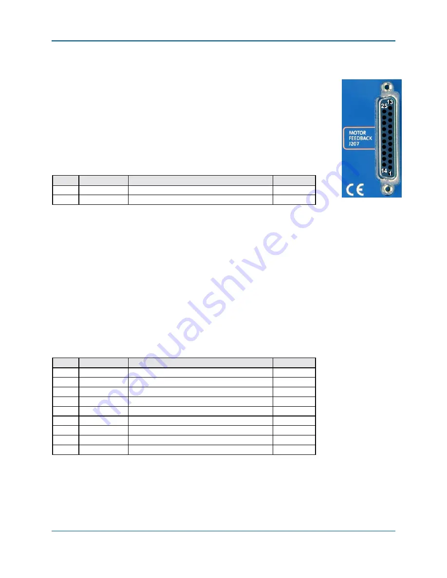
Table 3-16.
Motor Feedback Connector Pin Assignment (J207)
Pin #
Label
Description
In/Out/Bi.
1 Frame
Chassis
Frame
N/A
3
+5 Volt
+5 Volt Power for Encoder (500mA. max.)*
Output
6
Mkr -
Encoder Marker Reference Pulse -
Input
7
Mkr +
Encoder Marker Reference Pulse +
Input
14
Cos +
Encoder
Input
15
Cos -
Encoder Cosine -
Input
17
Sin +
Encoder Sine +
Input
18
Sin -
Encoder Sine -
Input
21
Common
Signal Common for Encoder
N/A
* Total user +5 V power is limited to 500 mA, by an internal re-settable semiconductor fuse.
All external power provided by the Ndrive HL to the user is protected by a re-settable
semiconductor fuse. Should an over-current condition occur, the device will open to
provide protection against the overload. To reset the over-current device, remove the
over-current condition.
Artisan Technology Group - Quality Instrumentation ... Guaranteed | (888) 88-SOURCE | www.artisantg.com