


Installation and Configuration
Ndrive HL User’s Manual
2-10
www.aerotech.com
2.4.3.1.
Brushless Motor Phasing
When configuring the Ndrive HL to run a non-Aerotech brushless motor, the motor leads
(A, B and C on TB101) must be correctly connected for proper operation. If an Aerotech
motor is used with Aerotech provided cabling, no motor phasing process is required.
If an Aerotech brushless motor is used with the Ndrive HL,
motor phase and HALL connections can be easily
determined by referring to the system interconnection
drawing in Figure 2-7.
Be sure to configure all axes with the Nparam.exe utility
before running the
A3200\Programs\Samples\MsetDebug.Pgm. See the
“Getting Started” section in the Nview help for
configuration information.
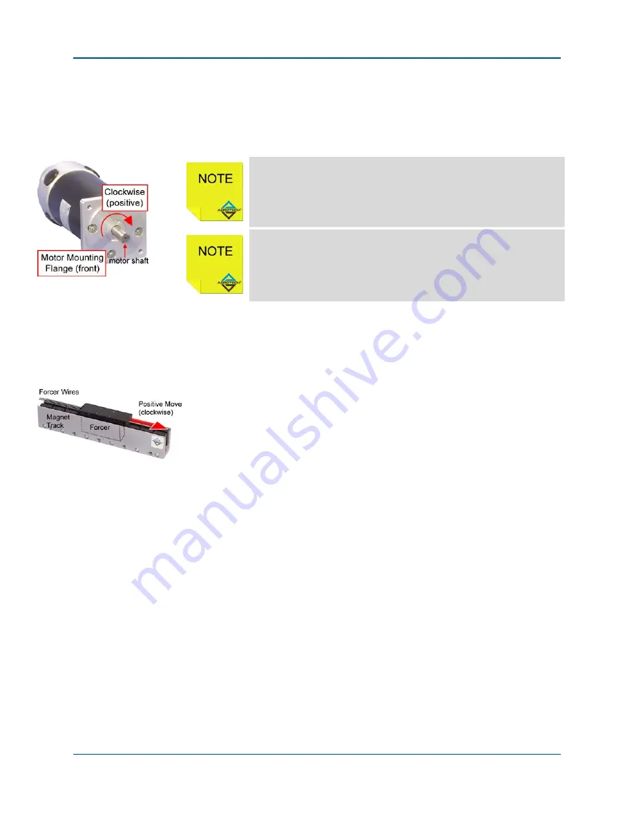
An AC brushless motor is correctly phased, when a positive motion command causes
clockwise (CW) motor rotation, as viewed looking at the motor from the front mounting
flange. This assumes a positive CntsPerMetricUnit/ CntsPerEnglishUnit
/CntsPerRotaryUnit axis parameter. This required phasing is determined by which motor
lead is connected to the ØA, ØB and ØC motor terminals.
Motor phasing is unrelated to the direction of motion commanded from within a motion
program. After correctly phasing the motor, you may reverse the motor direction when
commanding a positive move from a motion program, by negating the sign of the
CntsPerMetricUnit/CntsPerEnglishUnit/CntsPerRotaryUnit axis parameter.
Motor phasing may be determined by two methods. The first of which, is by actively
driving the motor open loop, under program control. The
A3200\Programs\Samples\MsetDebug.Pgm may be used for this purpose. The motor
phasing is correct when the program causes the motor to move in a positive direction, as
defined in Figure 2-13. Swapping any two motor lead connections will correct a reversed
motor rotation.
The second method is a non-powered method, whereby the motor is disconnected from
the controller and connected in the test configuration as defined in Figure 2-10 This will
identify motor (and Hall signal) leads A, B and C. These sequences and the generated
output motor phase voltages (motor output connections A, B, and C) are shown in
Figure
2-10. The voltages generated are made by moving the motor/forcer by hand in a positive
(CW) motion direction.
Artisan Technology Group - Quality Instrumentation ... Guaranteed | (888) 88-SOURCE | www.artisantg.com