BusWorks Model XT1531‐000
4 CH Current 4 CH Digital I/O w/USB & Modbus
Acromag, Inc. Tel: 248‐295‐0880
‐
49
‐
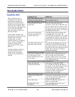
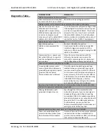
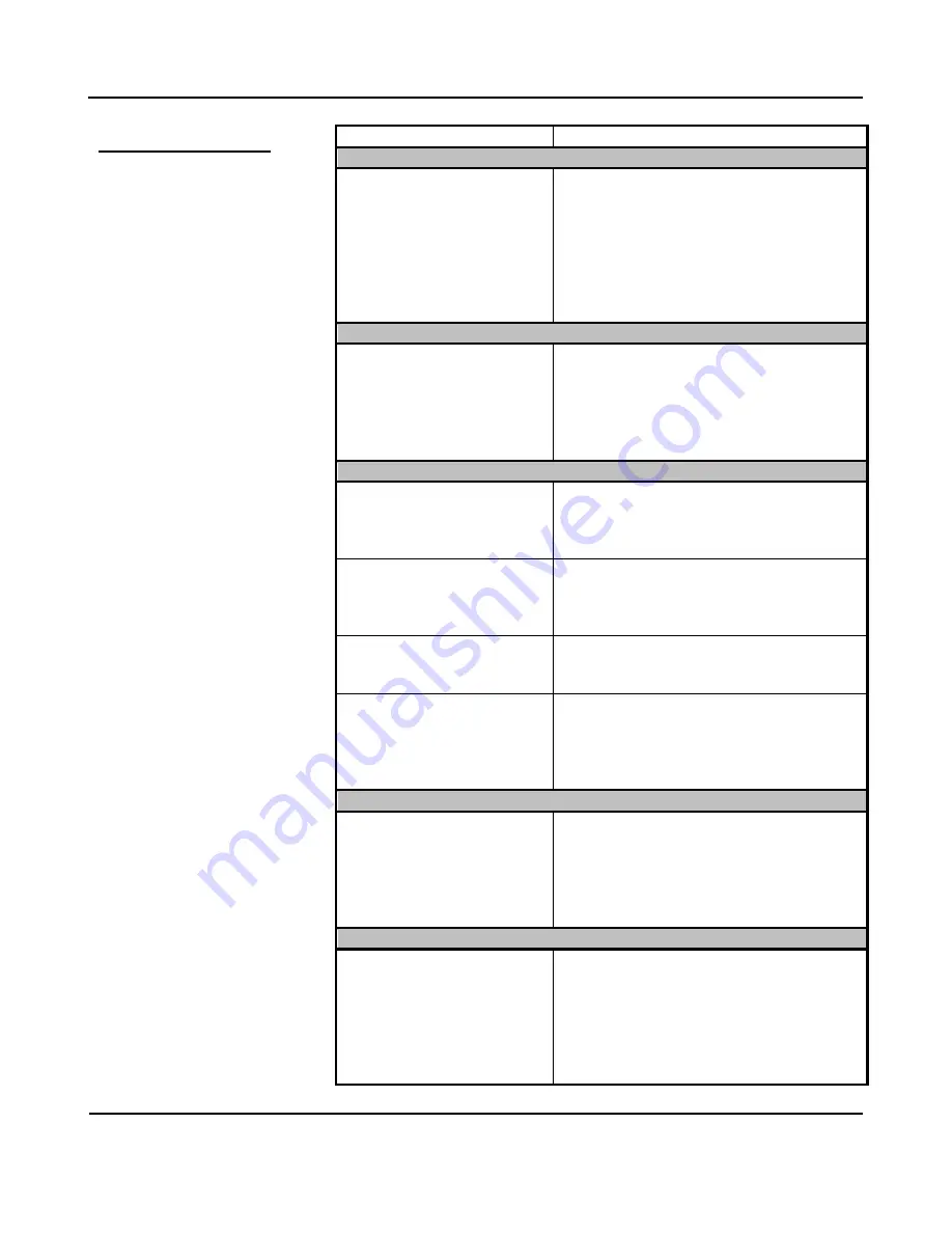
Diagnostics Table…
`
POSSIBLE CAUSE
POSSIBLE FIX
Continuous blinking yellow status LED…
Watchdog timer has timed out.
In the absence of a client‐server
relationship
over the network, such as that formed with
i2o, or between a Modbus master/client and
slave/server, a PLC or HMI and a server
module, the watchdog will timeout when
enabled, but can also timeout if a client‐server
relationship has been severed by a network
cable break, or power disruption at the client.
i2o is not working for your i2o input…
The upload was corrupted
when i2o was written to the
module.
Although rare, if you have rechecked your
input i2o configuration, and it still fails to
operate, try rebooting the input module, or re‐
writing your i2o configuration (check your
address settings, update time, change‐of‐
state, etc.).
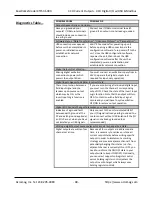
This i2o target is not working or working improperly…
The Holding Register address at
your i2o input module has
been specified wrong.
At your i2o source module, verify that you
have set the holding register address of the
target module correctly on its i2o
configuration page.
You have Coil Registers
enabled at your target.
You must disable the Coil Register control
mode at your target i2o output module to
allow its outputs to be programmed via an
input holding register.
Wrong control mode is set at
the i2o target.
Make sure your i2o target is using holding
register control mode, as opposed to coil
register control mode.
Your target output shut down
due to contention with a field
input signal.
Contention at the I/O channel triggers a
protection mechanism that causes the output
to turn OFF and you must cycle excitation
OFF/ON to the output to restore output
operation.
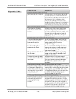
Cannot Get an i2o Source to Write the Digital Outputs On This Unit…
In your i2o sending unit, have
you specified a target starting
address that writes to the valid
input register of this model to
control its outputs?
This i2o target is returning errors because the
sending unit is trying to write beyond the valid
output register space at 40001. Refer to the
i2o Configuration Page of your i2o source and
verify that the Map to Holding Register
address is 40001 for this model.
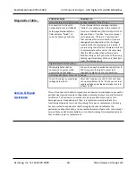
12V Analog Excitation Inputs Do Not Allow Output Operation…
The 12V excitation supply has
been damaged, typically by
connecting 24V to it by
mistake.
Connecting 24V power to the 12V analog
excitation terminals will destroy its TVS and
switching regulator. In this case, connect 24V
excitation (20‐28V) to the 24V terminals to
continue operation. If not having 12V analog
excitation is inconvenient, then you may
return your unit to Acromag for repair.

