BusWorks Model XT1531‐000
4 CH Current 4 CH Digital I/O w/USB & Modbus
Acromag, Inc. Tel: 248‐295‐0880
‐
30
‐
i2o Mapping…
With i2o, a client‐server network connection is established between a sending‐module (client) and a target output
module (server). This connection refers to an established data path, or socket, between the client input device and server
output
—it does not refer to just the physical network connection between devices. It is similar to other client‐server
network connections that are created for the exchange of data between devices, such as that between a Modbus Master
and slave, or that between a networked PLC, HMI, or other client device and its target server module.
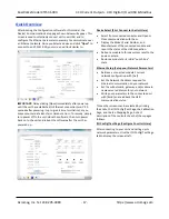
This model has four 4 digital I/O channels numbered 0, 1, 2, and 3. The 4 digital input channels may be mapped to a
corresponding group of 4 digital output channels on another compatible unit using i2o. Digital input data may be sent
cyclically according to an update time, and/or upon change of input state.
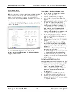
You can choose to maintain an i2o connection open by enabling Keep Socket Open, or instead to open and close the
connection for each i2o message. If Keep Socket Open is disabled, then you should specify an i2o Update Time at the
client (the sending module) that is less than the watchdog time of the server (the receiving output module), to ensure
that the server’s output watchdog does not time‐out during the period between i2o updates. Thus, it is generally
recommended that you Keep Sockets Open, except perhaps where it costs you money to maintain an open connection, or
if infrequent i2o messages might cause your server’s watchdog timer to
timeout.
The i2o messaging function works best if the target module(s) are already online and ready to receive messages.
However, it will still work if the target output module comes online after the input module, but may take several minutes
to “discover” the network targets and begin transmitting to them. If this input module or the target module(s) go offline,
remote i2o messaging will resume on its own when the connection is re‐established, but this “healing” function may take
several minutes depending on which device(s) went offline, why, and for how long.
It is not recommended to set an i2o update rate greater than 99 seconds while also choosing to “Keep Sockets Open”, as
increasing bandwidth and shortening response times is not a concern when cyclical messages are spaced farther than 99
seconds apart. But be conservative when setting update time
—
shorter intervals than needed may unnecessarily increase
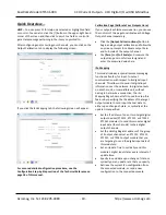
network traffic, while longer intervals will conserve network bandwidth. Note that digital inputs only map externally to
digital outputs of other target modules (at different IP addresses), and inputs are mapped in groups of four, to output
channels of the target device in groups of four, and in the same order. Each i2o message will write at least 4 digital
channels at a time.
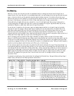
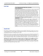
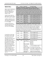
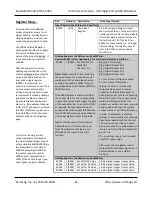
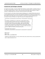
To summarize, the behavior of i2o is controlled by the configuration of Update Time, Change‐of‐State, and Keep Target
Sockets Open as illustrated in the following example combinations:
Update Time
Change‐of‐State
Keep Target Sockets Open
Behavior
0
Disabled
Enabled
i2o is OFF and no i2o messages are sent
0
Disabled
Disabled
i2o is OFF and no i2o messages are sent
0
Enabled
Enabled
Four inputs sent
every Change‐Of‐State (COS)
5‐99sec
Enabled
Enabled
Four inputs sent every COS & every interval of time
5‐99sec
Disabled
Enabled
Faster throughput w/four Inputs sent every interval
of update time
0
Enabled
Disabled
Four inputs sent only upon a
Change‐Of‐State
5‐65535sec
Disabled
Disabled
Four inputs sent every interval of Update Time
5‐65535sec
Enabled
Disabled
Four Inputs sent every COS & every interval of time
T > 99sec
Disabled
Enabled
Invalid Configuration w/ a long time over an open
socket. This will work but it is not recommended to
keep the socket open for infrequent i2o updates.


