BusWorks Model XT1531‐000
4 CH Current 4 CH Digital I/O w/USB & Modbus
Acromag, Inc. Tel: 248‐295‐0880
‐
33
‐
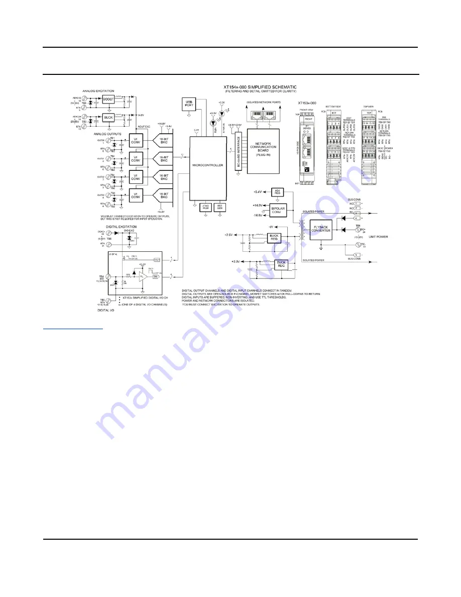
BLOCK DIAGRAM
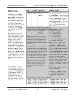
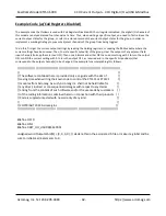
How It Works
Key Points of Operation
-
Unit is DC Powered.
−
You must connect excitation to
operate digital outputs.
−
You must connect excitation to
operate current outputs.
−
Outputs & Excitation share
Return.
−
Outputs & USB are Isolated from
the network and power.
−
Output Return is common to USB
Return/ground.
−
Analog outputs use 16‐bit DAC
conversion.
−
Digital Outputs source excitation
to the load
(active‐high).
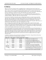
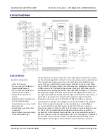
This model has four current output channels and four digital I/O channels. Outputs
use four 16‐bit voltage DACs to drive V/I current converters at each output channel.
This combinational model includes four smart high‐side power switches (open‐
source P‐ch
annel mosfets) that switch (source) excitation to a load, under digital
control of a 32‐bit microcontroller. Each output source is pulled down to return via
a 10KΩ resistor, and is fed back to the controller through a 100KΩ series resistor
which drives non
‐inverting input buffers with input diodes clamped to its +3.3V rail,
allowing input voltages well above the rail (up to 32V). Digital input channels use
TTL logic thresholds and feed back the actual state of the tandem output source, or
optionally an input state from the field, with its tandem output turned OFF.
Network communication specific to Modbus TCP/IP is handled by a separate
communication controller on a mating board, serial‐UART linked to the I/O board.
Power for the output and network circuits is provided via an isolated flyback
converter on the I/O board that operates from 12‐32V. The unit is setup for
network operation via USB connection to its I/O board microcontroller from a host
PC. The host PC runs model specific configuration software. By using USB to
configure the unit for network communication, it is not necessary to know the IP
address of the unit in order to communicate with it, nor to change the IP address of
your network card to match the module’s subnet address domain. Refer to the
block diagram above to gain a better understanding of how this model works.

