BusWorks Model XT1531‐000
4 CH Current 4 CH Digital I/O w/USB & Modbus
Acromag, Inc. Tel: 248‐295‐0880
‐
5
‐
output for other XT input models. i2o allows XT input channels to network‐link to
outputs of other BusWorks models via i2o messaging over the Ethernet network.
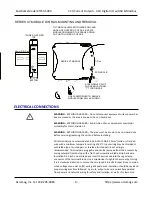
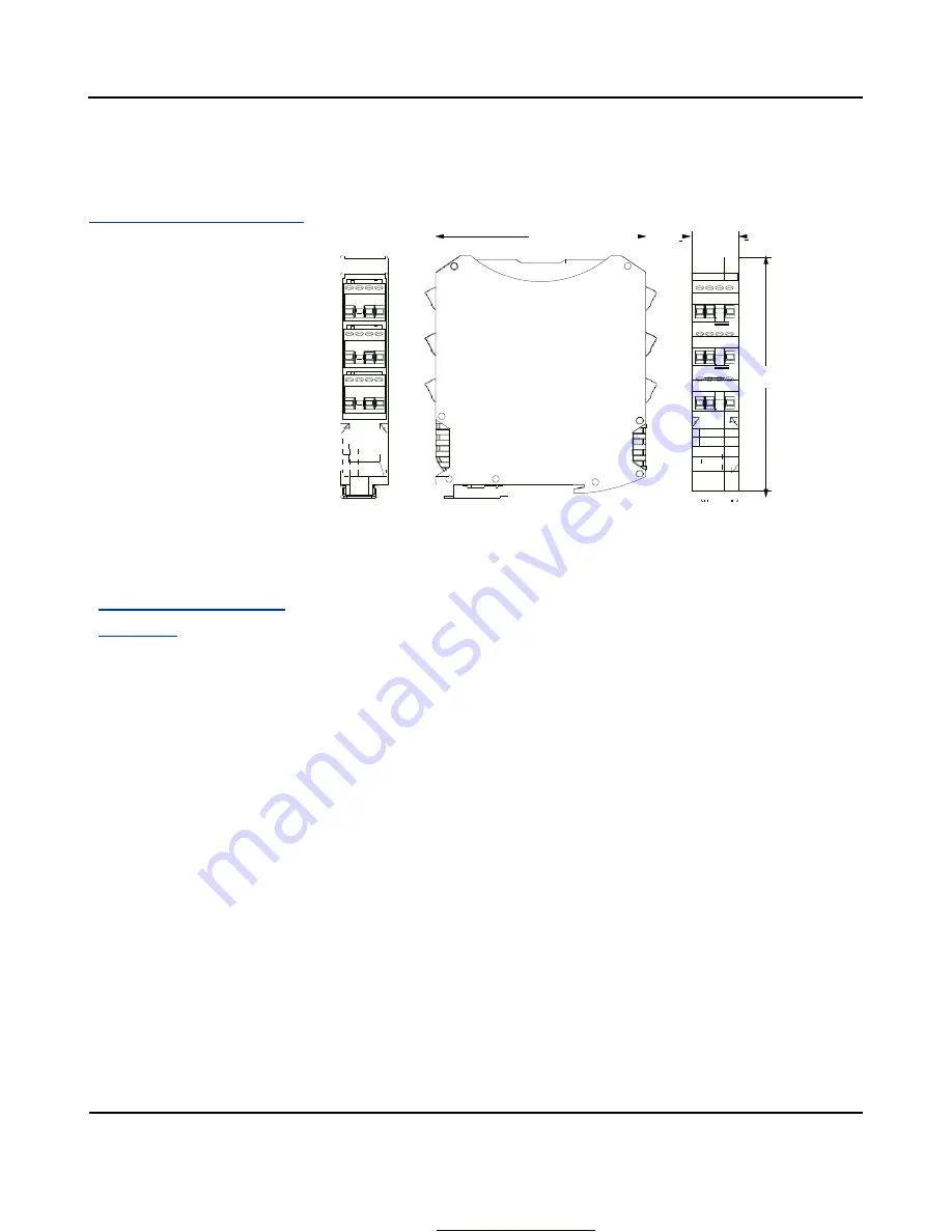
Mechanical Dimensions
Units may be mounted to 35mm
“T” type DIN rail (35mm, type
EN50022), and side‐by‐side on
22.5mm (0.9‐inch) centers.
WARNING:
IEC Safety Standards
may require that this device be
mounted within an approved
metal enclosure or sub‐system,
particularly for applications with
exposure to voltages greater than
or equal to 75VDC or 50VAC.
DIN Rail Mounting &
Removal
5
1)
DIMENSIONS ARE IN MILLIMETERS (INCHES)
Refer to the following figure for attaching and removing a unit from the DIN rail. A
spring loaded DIN clip is located on the bottom side. The opposite rounded edge at
the bottom of the top side allows you to tilt the unit upward to lift it from the rail
w
hile prying the spring clip back with a screwdriver. To attach the module to T‐type
DIN rail, angle the top of the unit towards the rail and place the top groove of the
module over the upper lip of the DIN rail. Firmly push the unit downward towards
the rail until it snaps into place. To remove it from the DIN rail, first separate the
input terminal blocks from the bottom side of the module to create a clearance to
the DIN mounting area. You can use a screwdriver to pry the pluggable terminals
out of their sockets. Next, while holding the module in place from above, insert a
screwdriver along the bottom side path of the module to the DIN rail clip and use it
as a lever to force the DIN rail spring clip down, while pulling the bottom of the
module outward until it disengages from the rail. Tilt it upward to lift it from the
rail.
IMPORTANT:
For ambient operation above 50°C, it is recommended to space units
apart to aide cooling. Module is intended to be mounted upright on a horizontal
DIN rail, allowing cool air to enter in through the bottom vents and warm air to
exhaust out the top vents. Above 50°C, a space of at least 20mm between modules
should be maintained to aide cooling in this manner.
IMPORTANT:
If your DIN rail is connected to a ground, a metal clip has been
installed in the back of this enclosure that makes contact with the DIN rail and
connects it to the input power DC
–
circuit. If your DIN rail ground is not common to
your power DC
–
ground, you should remove this clip to prevent a second
connection to ground via the DIN rail, which could generate a ground loop.
Connecting to one earth ground via the screw terminals on the unit is
recommended for best performance.
99.0
(3.90)
22.5
(0.89)
114.
(4.5


