BusWorks Model XT1531‐000
4 CH Current 4 CH Digital I/O w/USB & Modbus
Acromag, Inc. Tel: 248‐295‐0880
‐
39
‐
Data Types
DATA TYPES AND DESCRIPTIONS USED BY THIS MODEL
Discrete/Digital Data
Applies for R/W to Holding Registers, not Coil Registers, which are accessed using
coil register commands that do not operate directly on the register contents.
A discrete value is generally indicated by a single bit of a 16‐bit word. The bit
number (position) may correspond to the discrete channel number. For digital
outputs of this model, a set (1) bit means the corresponding output is sourcing
excitation to the output or ON, and a clear (0) bit means the output is open or
OFF. For digital inputs, a value of 1 means the input is ON (Active‐high above the
TTL threshold or greater than 2.0V), while a value of 0 specifies the input is OFF
or in its low state (below the TTL threshold or less than 0.8V).
This assumes that
the Input Logic Invert function is set to “No” or disabled.
Analog Data
A 16‐bit signed integer with a maximum possible range of ‐32768 to +32767. The
unipolar analog output ranges of this model are normalized to 0‐30000 or 0‐
20000 (w/legacy support selected), which represents 0‐100% of the pre‐defined
range. For example 0% and +100% are represented by decimal values 0, and
30000, respectively, or 0 and 20000 with Legacy Support enabled. The full
possible range is decimal 0‐109.2%, or 0‐32768 decimal. Thus, for this model,
20mA is driven with a raw register DAC count of 0 to 32768*(0.020*249/5.5254)
=29533. A 4mA range zero would correspond to 32768*(0.004*249/5.5254V)
=5907.
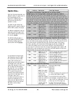
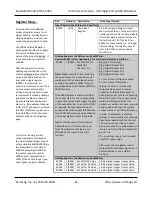
Register Map
This model has two different register maps, depending on the mode of digital output access you select. That is, you can
enable Coil Registers and use those registers to control digital I/O discretely, or you can disable Coil Registers and use a
Holding Register instead to control digital outputs as a group.
Modbus functions operate on the registers noted using the data types above (except for the Reset Slave and Report Slave
ID functions). The memory maps for this model covers reading analog and digital input data, and writing analog and
digital output data. There are no registers for setting any configuration variables, as this model is only configured via USB
using its Configuration Software running on a Windows based Personal Computer, prior to connecting to the network.
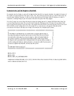
IMPORTANT: If this module is being used as an i2o target, support for Coil Registers must be disabled, or i2o will not
work (i2o writes are always written 4 channels at a time and always use a Holding Register to control the digital
outputs simultaneously).
The “Support Coil versus Holding Register for Digital Output Writes” option is a global setting
that applies to all digital outputs of a module. It is enabled or disabled from the Analog Output/Digital I/O Configuration
page of the USB Configuration Software for this model.


