BusWorks Model XT1531‐000
4 CH Current 4 CH Digital I/O w/USB & Modbus
Acromag, Inc. Tel: 248‐295‐0880
‐
16
‐
Earth Ground Connections
(To Protect Your Equipment, Lower
System Noise, and Reduce
Emissions)
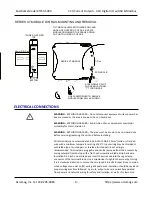
The unit housing is plastic and does not require an earth ground connection itself.
If the module is mounted in a metal housing, an earth ground wire connection to
the metal housing’s ground terminal (green screw) is usually required using suitable
wire per applicable codes. Circuits wired to inputs/outputs, power, and the
network should be earth grounded as well, as reflected in the connection diagrams.
The ground connections noted are recommended for best results and help protect
the unit by giving it a low impedance path to ground for shunting destructive
transient energy away from the module. See the Electrical Connection Drawings for
recommended input/output, power, and network ground connections.
IMPORTANT:
For units mounted to DIN rail, a metal clip has been installed in the
back of this enclosure and it makes contact with the DIN rail and connects it to the
input power DC
–
circuit. If your DIN rail ground is not common to your power DC
–
ground, you should carefully pry the enclosure apart and remove this clip to prevent
a second connection to ground via the DIN rail. Connecting to one earth ground via
the screw terminals on the unit is recommended for best performance.
Note:
A USB isolator is recommended when connected to a grounded Personal
Computer for configuration purposes. This will avoid an inadvertent ground loop
that will occur if your input signal is already earth grounded, as a PC commonly
earth grounds its USB port and this makes contact with both the USB signal and
shield ground which is held in common to the input circuit return of this module.
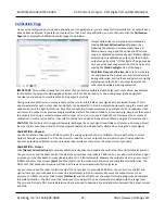
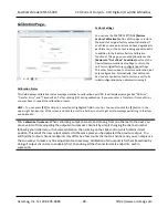
CONFIGURATION SOFTWARE
While this is an Ethernet network I/O module, it can only be configured and calibrated via its Configuration Software over
a USB connection to a Windows‐based PC or laptop. USB saves you the trouble of having to already know its IP address
setting, or having to change the address setting of your network interface card to match its address domain in order to
communicate with it. USB software is contained in a zip file that can be downloaded free of charge from our web site at
Look for the software zip file 9500465 in the Documents and Downloads page for your XT
product. Initially, you will have to answer a few questions to open a user account and download this file to your
computer. This zip file will extract to a
modelconfig.exe
executable file installed in an Acromag subdirectory off the
Program Files directory of your PC. Note that you must have administrator rights to download and install this software
onto your PC or laptop.
Once you have installed the software, be sure to navigate to the
Program Files\Acromag
subdirectory and select the
correct
modelconfig.exe
software for your particular module. This same software is also included on a CDROM bundled in
the Configuration Kit XT‐SIP (see Accessories), but downloading it from the web will he
lp to ensure that your software is
the most up‐to‐date available. This software is compatible with XP or later versions of the Windows operating system.
Note that the particular
modelconfig.exe
software for this unit supports five other combinational model variations
—
three
models with 8 voltage outputs, plus three models with 4 current outputs, each including 4 sourcing digital I/O channels.


