BusWorks Model XT1531‐000
4 CH Current 4 CH Digital I/O w/USB & Modbus
Acromag, Inc. Tel: 248‐295‐0880
‐
55
‐
Digital Outputs
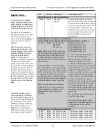
This model has four tandem
digital input and output channels.
Excitation for the sourcing digital
outputs is required at TB6 to
operate them.
To control higher voltages and/or
currents, or for controlling AC, an
interposing relay may be used
(see Note).
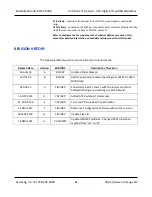
This model has four open‐source, smart, p‐channel mosfet switches with a common
drain connection to the dig
ital excitation source at TB6‐22. It provides high‐side
switching between the digital excitation and the load connected between the output
channel at TB4 and return at TB5. It is intended for DC voltage sourcing applications
only. The outputs will drive any rated load up to 250mA with one side connected
return. Outputs have tandem inputs which provide true loopback monitoring of the
output state, or the inputs can be used to monitor field inputs with the output OFF.
Individual I/O channels are pulled down to I/O Return (connected at RTN terminal)
with 10KΩ resistors and do not float. External excitation is required for digital output
operation and this is connected between the EXC and RTN terminals of TB6 (terminal
numbers 22 and 21 respectively).
Digital O
utput “OFF” Voltage Range:
0 to 32V DC. Limit voltage to less than 36V
peak, or damage to the unit may result. Use protection when switching inductive
loads (for example, use a reverse shunt diode at the inductive load).
Output Active Current Limitation:
The unit limits load current to a shorted load to
0.6A typical, 0.4A‐0.9A range (EXC=13V and 0.01Ω load resistance). This limit works
with a latched thermal shutdown to help protect the output channel from damage
due to overload (cycle excitation OFF/ON to restore output operation after a
shutdown).
Output Thermal Shutdown:
Individual outputs will shutdown and latch off for
thermal overload conditions that drive the junction temperature into the region from
150° to 200°C. If your outputs stop working, the I/O pin is pulled low and the output
must be cycled OFF/ON to restore operation.
Output Under‐voltage Shutdown:
Outputs will shut‐down if their excitation voltage
is less than 6.0V (3V‐6V threshold).
Output Overvoltage Shutdown:
Outputs will
shut‐down if their excitation voltage
exceeds 36V minimum.
Output Ground Loss Protection:
The output automatically turns off if the ground
lead is disconnected (RTN).
Output “OFF” Leakage Current:
50uA maximum per channel (mosfet only). Does
not include the input bias current for the tandem digital input (see Note below).
Note:
The 100K
series input buffer resistors in combination with the +3.3V voltage
diode clamps at the input buffer will tend to increase the off‐state current with
increasing output voltage (up to 3.5mA at 32V). This is a consequence of the input
buffer circuitry being connected in tandem to the output mosfet source lead at every
I/O channel, and the presence of a 10KΩ pull‐down on the
input.
Output “ON” Current Range:
0 to 250mA DC, continuous (up to 1A total for all 4
channels combined). No deration is required at elevated ambient. Match one TB5
return (RTN) to each of 4 output loads.
Output R
ds
ON Resistance:
0.5
typical at 0.25A and 25°C, 1.0
Maximum.
Output Response Time:
10ms typical. Does not include network time. The actual
output switch time will vary with network traffic, interrupts, and output load.
Note:
Per UL, when the outputs are used to control interposing relays for switching
AC and DC devices of higher voltage/current, the coil ratings for the interposing relay
shall not exceed 24VDC, 100mA.

