BusWorks Model XT1531‐000
4 CH Current 4 CH Digital I/O w/USB & Modbus
Acromag, Inc. Tel: 248‐295‐0880
‐
41
‐
Register Map…
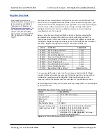
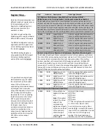
This model has two different
modes of register access for its
digital outputs, Coil Registers or
Holding Registers, and only one
mode may be enabled at a time.
The 40001 Holding Register is
only applicable with the Support
Coil versus Holding registers
option of the module disabled. It
is not used with coil registers
enabled.
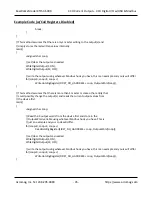
With the Support Coil versus
Holding registers option of the
module disabled, all four digital
outputs are addressed at one
time with a single register
(40001). In this mode, it is
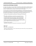
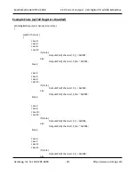
necessary to retrieve or store the
current output states before
writing a specific output in order
to implement a masking strategy
and prevent adjacent channel’s
from potentially changing their
states (i.e. if an adjacent channel
is ON or Off, you need to reinforce
the ON or OFF state in your write
to keep it ON or OFF). See some
example code on the following
page.
For the four analog current
output channels of this model,
the 16‐bit signed integer output
values stored in 40002‐40009 are
the normalized counts with 0‐
30000 representing 0‐100% of
the o
utput range (or with 0‐
20000 counts representing 0‐
100% of the output range if you
have legacy support enabled).
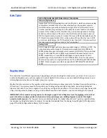
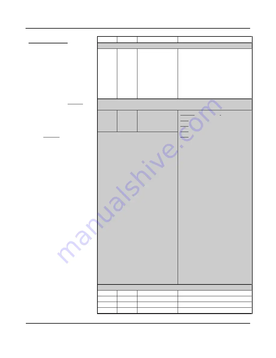
Ref.
Address Description
Data Type/Format
Input Registers (3x References, Read‐Only)
3
0002
0001
Heart Beat
Register
A 16‐bit unsigned integer counter
that increments by 1 for every host to
network data transfer to help indicate
if fresh I/O data is present relative to
the last transfer, or if the unit has
halted for some reason (i.e. no longer
incrementing). This register counts
from 0 to 65535 and wraps back
around to 0.
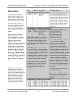
Holding Registers (4x References, Read/Write) ‐
Register 40001 is Only Applicable if the Coil Register Option is Disabled
40001
0 (0000) Set DO State for
Digital I/O
Channels 0‐3
Bit 15‐4
: 0 (Not Used)
Bit 3: Digital Output CH3
Bit 2: Digital Output CH2
Bit 1: Digital Output CH1
Bit 0: Digital Output CH0
1 = Turn Output ON (Source Load)
0 = Turn Output OFF (Open)
Setting the bit to 1 will drive the
corresponding output to source
excitation to the load (conducts or
sinks load current to return). Clearing
the bit to 0 means the output will be
switched OFF (open). Since four
outputs are written at a time, you will
need to either retrieve the current
output states, or store the last states,
in order to implement a masking
strategy to prevent adjacent channels
from being toggled with the channel
of interest when writing an output.
All input channels are pulled‐down to
return and will not float. Unused bits
are set to 0.
The Invert Input Logic function does
not affect output logic.
After reset, these registers read 0
(outputs OFF) and these registers are
not maintained in non‐volatile
memory.
Note:
Digital outputs of this model are
the open sources of p‐channel mosfet
switches with their drain leads held in
common to excitation (EXC). Outputs
are pulled down to I/O Return (RTN) via
10KΩ resistors.
The 40001 register is used to set/clear
the output states of the corresponding
output channels and will trigger the gate
of the output mosfet to turn ON or OFF,
as required. Output channels source
excitation from the output to RTN when
turned ON. Failure to provide excitation
will render digital outputs inoperable.
Digital I/O channels of this model are
pulled down to I/O return and never
float. The digital output logic is not
affected by the Invert Input Logic
function.
Holding Registers (4x References, Read/Write)
40002
1 (0001) Set AO CH00 Value
16‐bit Signed Integer Output Value
40003
2 (0002) Set AO CH 01 Value
16‐bit Signed Integer Output Value
40004
3 (0003) Set AO CH 02 Value
16‐bit Signed Integer Output Value
40005
4 (0004) Set AO CH 03 Value
16‐bit Signed Integer Output Value

