Chapter 4
168
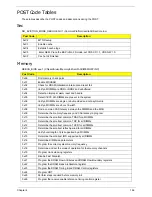
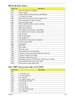
BDS & Specific action:
Each PEIM entry point used in 80_PORT
Post Code
Description
0x00
Report the legacy boot is happening
0x12
Wake up the Aps
0x13
Initialize SMM Private Data and relocate BSP SMBASE
0x21
PC init begin at the stage1
0x27
Report every memory range do the hard ware ECC init
0x28
Report status code of every memory range
0x50
Get the root bridge handle
0x51
Notify pci bus driver starts to program the resource
0x58
Reset the host controller
0x5A
IdeBus begin initialization
0x79
Report that the remote terminal is being disabled
0x7A
Report that the remote terminal is being enabled
0x90
Keyboard reset
0x91
USB Keyboard disable
0x92
Keyboard detection
0x93
Report that the usb keyboard is being enabled
0x94
Clear the keyboard buffer
0x95
Init Keyboard
0x98
Mouse reset
0x99
Mouse disable
0x9A
Detect PS2 mouse
0x9B
Report that the mouse is being enabled
0xB8
Peripheral removable media reset(ex:IsaFloppy, USB device)
0xB9
Peripheral removable media disable
0xBB
Peripheral removable media enable
0xE4
Report Status Code here for DXE_ENTRY_POINT once it is available
0xF8
Report that ExitBootServices() has been called
0xF9
Runtime driver set virtual address map
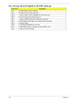
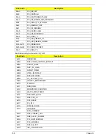
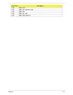
Post Code
Description
0x00
0x01
PEI_EVENT_LOG
0xA1
PEI_OEM_SERVICE
0xA2
PEI_SIO_INIT
0xA3
PEI_MONO_STATUS_CODE
0xA4
PEI_CPU_IO_PCI_CFG
0x06
PEI_CPU_IO
0x07
PEI_PCI_CFG
0xA5
PEI_CPU_PEIM
0xA6
PEI_PLATFORM_STAGE1
0xA7
PEI_VARIABLE
Содержание Aspire 5534 Series
Страница 6: ...VI ...
Страница 10: ...X Table of Contents ...
Страница 31: ...Chapter 1 21 Pack capacity 4400 mAh Number of battery cells 6 Package configuration 3S2P Item Specification ...
Страница 32: ...22 Chapter 1 ...
Страница 51: ...Chapter 2 41 ...
Страница 52: ...42 Chapter 2 ...
Страница 65: ...Chapter 3 55 ...
Страница 71: ...Chapter 3 61 6 Open the Keyboard FFC securing latch as shown then disconnect the FFC and remove the Keyboard ...
Страница 79: ...Chapter 3 69 ...
Страница 81: ...Chapter 3 71 5 Lift the Power Board from the Lower Cover ...
Страница 83: ...Chapter 3 73 6 Lift the right side speaker out from the Lower Cover as shown ...
Страница 89: ...Chapter 3 79 7 Disconnect the I O Board Cable from the I O Board ...
Страница 97: ...Chapter 3 87 ...
Страница 103: ...Chapter 3 93 ...
Страница 107: ...Chapter 3 97 6 Disconnect the LCD cable as shown and remove the cable from the LCD Panel ...
Страница 110: ...100 Chapter 3 ...
Страница 125: ...Chapter 3 115 3 Grasp the Thermal Module by the CPU heat sink and place onto the Mainboard as shown ...
Страница 197: ...Chapter 6 187 ...
Страница 224: ...214 ...

