18
Chapter 1
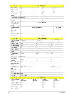
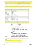
Super-Multi Drive Module
BIOS
Item
Specification
Vendor & model name
HLDS GU10N
PANASONIC UJ892
Performance
Specification
With CD Diskette
With DVD Diskette
With CD Diskette
With DVD Diskette
Transfer rate (MB/sec)
Sustained:
.
Sustained:
Sustained:
Sustained:
Buffer Memory
Interface
SATA
Applicable disc formats
•
CD R/RW
•
DVD R/RW
Loading mechanism
Emergency Release (draw open hole)
Power Requirement
Input Voltage
DC 5 V +/- 5%
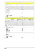
Item
Specification
Vendor & model name
TOSHIBA Super-Multi DRIVE 9.5mm Tray DL
8X TS-U633A LF W/O bezel SATA GBAS2.0
Performance
Specification
With CD Diskette
With DVD Diskette
Transfer rate (MB/sec)
Sustained:
3,600 KB/sec
Sustained:
10,800 KB/sec
Buffer Memory
2 MB
Interface
SATA
Applicable disc formats
•
CD R/RW
•
DVD R/RW
Loading mechanism
Emergency Release (draw open hole)
Power Requirement
Input Voltage
DC 5 V +/- 5%
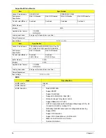
Item
Specification
BIOS vendor
Insyde
BIOS Version
3.5
BIOS Features
•
Flash ROM 1MB
•
Support ISIPP
•
Support multi-boot
•
Suspend to RAM (S3) / Disk (S4)
•
Various hot-keys for system control
•
Support SMBUS 2.0, PCI2.3
•
ACPI 2.0 compliance with Intel Speed Step Support C1e, C2,
C3 and S3, S4,S5 for mobile CPU.
•
DMI utility for BIOS serial number configuration/asset tag
•
Support PXE
•
Support Y2K solution
•
Support Win Flash Wake on LAN from S3
•
Wake on LAN form S4 in AC mode
•
System information
Содержание Aspire 5534 Series
Страница 6: ...VI ...
Страница 10: ...X Table of Contents ...
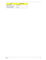
Страница 31: ...Chapter 1 21 Pack capacity 4400 mAh Number of battery cells 6 Package configuration 3S2P Item Specification ...
Страница 32: ...22 Chapter 1 ...
Страница 51: ...Chapter 2 41 ...
Страница 52: ...42 Chapter 2 ...
Страница 65: ...Chapter 3 55 ...
Страница 71: ...Chapter 3 61 6 Open the Keyboard FFC securing latch as shown then disconnect the FFC and remove the Keyboard ...
Страница 79: ...Chapter 3 69 ...
Страница 81: ...Chapter 3 71 5 Lift the Power Board from the Lower Cover ...
Страница 83: ...Chapter 3 73 6 Lift the right side speaker out from the Lower Cover as shown ...
Страница 89: ...Chapter 3 79 7 Disconnect the I O Board Cable from the I O Board ...
Страница 97: ...Chapter 3 87 ...
Страница 103: ...Chapter 3 93 ...
Страница 107: ...Chapter 3 97 6 Disconnect the LCD cable as shown and remove the cable from the LCD Panel ...
Страница 110: ...100 Chapter 3 ...
Страница 125: ...Chapter 3 115 3 Grasp the Thermal Module by the CPU heat sink and place onto the Mainboard as shown ...
Страница 197: ...Chapter 6 187 ...
Страница 224: ...214 ...

