Chapter 3
45
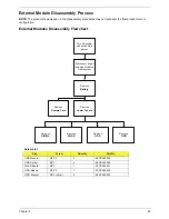
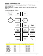
External Module Disassembly Process
NOTE:
The product previews seen in the disassembly procedures may not represent the final product color or
configuration.
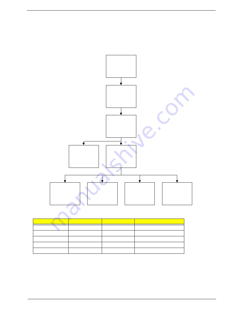
External Modules Disassembly Flowchart
Screw List
Step
Screw
Quantity
Part No.
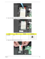
HDD Module
M2.5*3
2
86.PEA02.003
HDD Carrier
M3*3
4
86.PEA02.008
WLAN Board
M2*3
1
86.PEA02.001
ODD Module
M2.5*3
1
86.PEA02.009
ODD Bracket
M2*3 (silver)
2
86.PEA02.002
Disconnect power
and signal cables
from system
Remove
Battery
Turn off system
and peripherals
power
Remove
DIMMs
Remove
WLAN
Remove
HDD
Remove
ODD
Remove
Lower Covers
Remove
Dummy Card
Содержание Aspire 5534 Series
Страница 6: ...VI ...
Страница 10: ...X Table of Contents ...
Страница 31: ...Chapter 1 21 Pack capacity 4400 mAh Number of battery cells 6 Package configuration 3S2P Item Specification ...
Страница 32: ...22 Chapter 1 ...
Страница 51: ...Chapter 2 41 ...
Страница 52: ...42 Chapter 2 ...
Страница 65: ...Chapter 3 55 ...
Страница 71: ...Chapter 3 61 6 Open the Keyboard FFC securing latch as shown then disconnect the FFC and remove the Keyboard ...
Страница 79: ...Chapter 3 69 ...
Страница 81: ...Chapter 3 71 5 Lift the Power Board from the Lower Cover ...
Страница 83: ...Chapter 3 73 6 Lift the right side speaker out from the Lower Cover as shown ...
Страница 89: ...Chapter 3 79 7 Disconnect the I O Board Cable from the I O Board ...
Страница 97: ...Chapter 3 87 ...
Страница 103: ...Chapter 3 93 ...
Страница 107: ...Chapter 3 97 6 Disconnect the LCD cable as shown and remove the cable from the LCD Panel ...
Страница 110: ...100 Chapter 3 ...
Страница 125: ...Chapter 3 115 3 Grasp the Thermal Module by the CPU heat sink and place onto the Mainboard as shown ...
Страница 197: ...Chapter 6 187 ...
Страница 224: ...214 ...

