130
Chapter 3
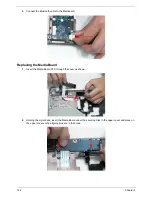
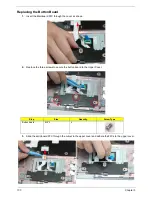
Replacing the Button Board
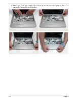
1.
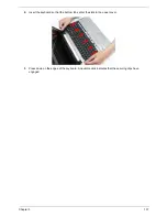
Insert the Mainboard FFC through the cover as shown.
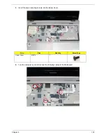
2.
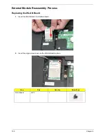
Replace the three screws to secure the button board to the Upper Cover.
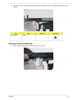
3.
Slide the aminboard FFC through the cutout in the upper cover and adhere the FFCs to the upper cover.
Step
Size
Quantity
Screw Type
Button Board
M2*3
4
Содержание Aspire 5534 Series
Страница 6: ...VI ...
Страница 10: ...X Table of Contents ...
Страница 31: ...Chapter 1 21 Pack capacity 4400 mAh Number of battery cells 6 Package configuration 3S2P Item Specification ...
Страница 32: ...22 Chapter 1 ...
Страница 51: ...Chapter 2 41 ...
Страница 52: ...42 Chapter 2 ...
Страница 65: ...Chapter 3 55 ...
Страница 71: ...Chapter 3 61 6 Open the Keyboard FFC securing latch as shown then disconnect the FFC and remove the Keyboard ...
Страница 79: ...Chapter 3 69 ...
Страница 81: ...Chapter 3 71 5 Lift the Power Board from the Lower Cover ...
Страница 83: ...Chapter 3 73 6 Lift the right side speaker out from the Lower Cover as shown ...
Страница 89: ...Chapter 3 79 7 Disconnect the I O Board Cable from the I O Board ...
Страница 97: ...Chapter 3 87 ...
Страница 103: ...Chapter 3 93 ...
Страница 107: ...Chapter 3 97 6 Disconnect the LCD cable as shown and remove the cable from the LCD Panel ...
Страница 110: ...100 Chapter 3 ...
Страница 125: ...Chapter 3 115 3 Grasp the Thermal Module by the CPU heat sink and place onto the Mainboard as shown ...
Страница 197: ...Chapter 6 187 ...
Страница 224: ...214 ...

