Chapter 2
33
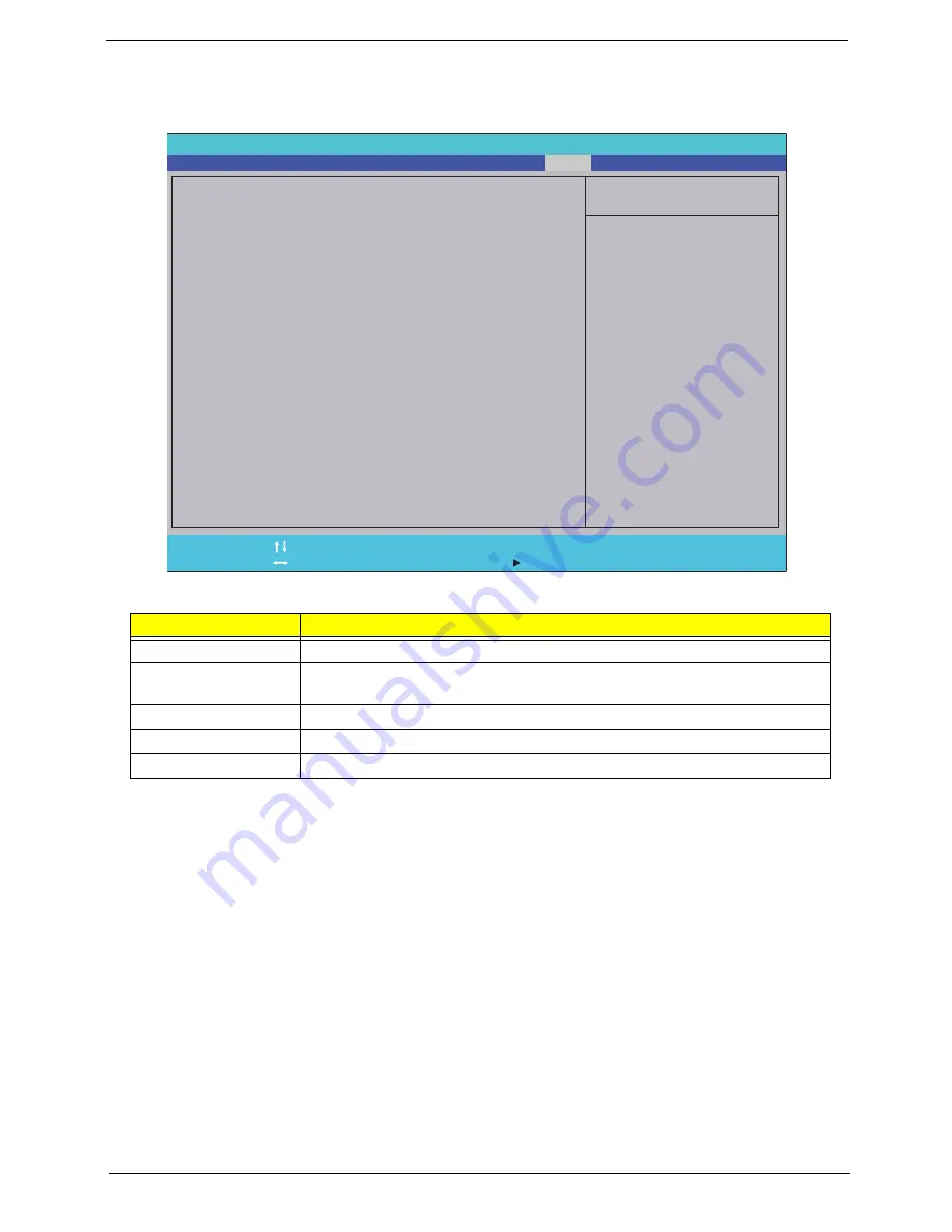
Exit
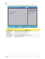
The Exit screen allows you to save or discard any changes you made and quit the BIOS Utility.
The table below describes the parameters in this screen.
Parameter
Description
Exit Saving Changes
Exit System Setup and save your changes to CMOS.
Exit Discarding
Changes
Exit utility without saving setup data to CMOS.
Load Setup Default
Load default values for all SETUP item.
Discard Changes
Load previous values from CMOS for all SETUP items.
Save Changes
Save Setup Data to CMOS.
I t e m S p e c i f i c H e l p
E x i t S y s t e m S e t u p a n d
s a v e y o u r c h a n g e s t o
C M O S .
F 1
E S C
H e l p
E x i t
S e l e c t I t e m
S e l e c t M e n u
C h a n g e Va l u e s
S e l e c t
S u b M e n u
E n t e r
F 9
F 10
S e t u p D e f a u l t
S a v e a n d E x i t
E x i t S a v i n g C h a n g e s
E x i t D i s c a r d i n g C h a n g e s
L o a d S e t u p D e f a u l t s
D i s c a r d C h a n g e s
S a v e C h a n g e s
E x i t S a v i n g C h a n g e s
E x i t D i s c a r d i n g C h a n g e s
L o a d S e t u p D e f a u l t s
D i s c a r d C h a n g e s
S a v e C h a n g e s
F 5 / F 6
I n s y d e H 2 0 S e t u p U t i l i t y R e v . 3 . 5
Information
Advanced
Main
Boot
Exit
Security
Power
Содержание Aspire 5534 Series
Страница 6: ...VI ...
Страница 10: ...X Table of Contents ...
Страница 31: ...Chapter 1 21 Pack capacity 4400 mAh Number of battery cells 6 Package configuration 3S2P Item Specification ...
Страница 32: ...22 Chapter 1 ...
Страница 51: ...Chapter 2 41 ...
Страница 52: ...42 Chapter 2 ...
Страница 65: ...Chapter 3 55 ...
Страница 71: ...Chapter 3 61 6 Open the Keyboard FFC securing latch as shown then disconnect the FFC and remove the Keyboard ...
Страница 79: ...Chapter 3 69 ...
Страница 81: ...Chapter 3 71 5 Lift the Power Board from the Lower Cover ...
Страница 83: ...Chapter 3 73 6 Lift the right side speaker out from the Lower Cover as shown ...
Страница 89: ...Chapter 3 79 7 Disconnect the I O Board Cable from the I O Board ...
Страница 97: ...Chapter 3 87 ...
Страница 103: ...Chapter 3 93 ...
Страница 107: ...Chapter 3 97 6 Disconnect the LCD cable as shown and remove the cable from the LCD Panel ...
Страница 110: ...100 Chapter 3 ...
Страница 125: ...Chapter 3 115 3 Grasp the Thermal Module by the CPU heat sink and place onto the Mainboard as shown ...
Страница 197: ...Chapter 6 187 ...
Страница 224: ...214 ...

