Acer Altos R700 Series Скачать руководство пользователя страница 52

 3 Installing the System in a Rack

44

Your Altos R700 chassis comes equipped with a rack mount kit that can 
be configured for front-mount, mid-mount, or 4-post racks. An 
optional slide rail kit may be purchased separately.

Equipment Rack Precautions
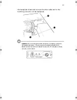
Caution

:

ANCHOR THE EQUIPMENT RACK

: The equipment rack must be 

anchored to an unmovable support to prevent it from falling over 
when one or more servers are extended in front of it on slide 
assemblies. The equipment rack must be installed according to the 
manufacturer's instructions. You must also consider the weight of 
any other device installed in the rack.

MAIN AC POWER DISCONNECT

: You are responsible for 

installing an AC power disconnect for the entire rack unit. This 
main disconnect must be readily accessible, and it must be labeled 
as controlling power to the entire unit, not just to the server(s).

GROUNDING THE RACK INSTALLATION

: To avoid the potential 

for an electrical shock hazard, you must include a third wire safety 
grounding conductor with the rack installation. If server power 
cords are plugged into AC outlets that are part of the rack, then 
you must provide proper grounding for the rack itself. If server 
power cords are plugged into wall AC outlets, the safety 
grounding conductor in each power cord provides proper 
grounding only for the server. You must provide additional, 
proper grounding for the rack and other devices installed in it.

OVER CURRENT PROTECTION

: The server is designed for an AC 

line voltage source with up to 20 amperes of over current 
protection. If the power system for the equipment rack is installed 
on a branch circuit with more than 20 amperes of protection, you 
must provide supplemental protection for the server. If more than 
one server is installed in the rack, the power source for each server 
must be from a separate branch circuit.

Temperature

: The operating temperature of the server, when 

installed in an equipment rack, must not go below 5 °C (41 °F) or 
rise above 35 °C (95 °F). Extreme fluctuations in temperature can 
cause a variety of problems in your server.

AR700-e.book  Page 44  Tuesday, September 10, 2002  2:31 PM

Содержание Altos R700 Series

Страница 1: ...Altos R700 Chassis Subassembly Product guide...

Страница 2: ...d to your computer All correspondense concerning your unit should include the serial number model number and purchase information No part of this publication may be reproduced stored in a retrieval sy...

Страница 3: ...at personal expense Class B equipment This device has been tested and found to comply with the limits for a Class B digital device pursuant to Part 15 of the FCC Rules These limits are designed to pr...

Страница 4: ...ption Caution Changes or modifications not expressly approved by the manufacturer could void the user s authority which is granted by the Federal Communications Commission to operate this server Use c...

Страница 5: ...king label If you are not sure of the type of power available consult your dealer or local power company 7 Do not allow anything to rest on the power cord Do not locate this product where persons will...

Страница 6: ...indicating a need for service 12 Replace the battery with the same type as the product s battery we recommend Use of another battery may present a risk of fire or explosion Refer battery replacement...

Страница 7: ...on Assembly Safety Instructions 18 Use Only for Intended Applications 18 Checking the Power Cord 19 Warnings and Cautions 19 Installing System Components 21 Remove the Cover 21 Remove the Processor Ai...

Страница 8: ...VD CD ROM drive FDD Module 52 Replacing a PCI Add in Card 54 Replacing a 500 Watt Power Supply Module 56 Replacing a Power Supply Cage 57 Installing a Redundant Fan 59 Replacing the Fan Module 61 Repl...

Страница 9: ...1 Chassis Description...

Страница 10: ...One bay for optional tape drive comes with carrier and filler panel One 480 W SSI PFC non redundant power supply or a 500 W 1 0 SSI PFC redundant power supply with one module and one blank Two PCI ri...

Страница 11: ...mline DVD CD ROM drive floppy disk drive module optional PCI add in cards Hard drive carriers over the four supplied 500 W power supply module for redundancy System fan for redundancy Other peripheral...

Страница 12: ...Label Description A Power supply B PCI card bracket full lenght C Riser card assembly full lenght D PCI card bracket low profile E Server board accessory to system F PCI add in card accessory to syst...

Страница 13: ...ntil it unsnaps from the chassis I Front panel board J Intrusion switch K Control panel L Flex bay optional DVD CD ROM drive FDD module available M Tape drive bay tape drive available from others N Ha...

Страница 14: ...e drive not included Label Description A PCI card bracket low profile B RJ45 NIC 2 connector Green Status LED Yellow Status LED C Serial A port mounting hole cable not provided D PCI card bracket full...

Страница 15: ...and Indicators Shown with optional DVD CD ROM drive floppy disk drive installed J RJ45 serial port K PS 2 mouse keyboard connector L RJ45 NIC 1 connector M SCSI channel A connector If available N Vide...

Страница 16: ...1 Chassis Description 8 C Power sleep LED D Fixed disk drive status LED E System status LED F ID LED G ID button H Reset button I USB Connector J NMI button K Video Connector Label Description...

Страница 17: ...k of servers Power sleep LED Continuous green light indicates the system has power applied to it Blinking green light Note 4 indicates the system is sleeping No light indicates the system does not hav...

Страница 18: ...by the chipset If the system is powered down without going through BIOS the LED state in effect at the time of power off will be restored when the system is powered on until the BIOS clears it If the...

Страница 19: ...ilable options Hot Swappable SCSI Hard Drives The chassis ships with four drive carriers for mounting SCSI hard drives in the hard drive bays For information on how to install these drives see Install...

Страница 20: ...f It is NOT hot swappable For information on installation see Installing a DVD drive FDD or CD ROM drive FDD Module on page 39 500 Watt Redundant Power Supply The power supply consists of the power su...

Страница 21: ...nt software When the cover is opened the switch located on the front panel board transmits a signal to the Baseboard Management Controller BMC on the server board where server management software proc...

Страница 22: ...1 Chassis Description 14...

Страница 23: ...2 Assembling the System...

Страница 24: ...stem The following procedures help guide you through this assembly process and create your desired system configuration Note To maintain and ensure regulation compliance the fully integrated system sh...

Страница 25: ...have the following supplies available Anti static wrist strap recommended Altos R700 accessory kit included Altos R700 Server Board Processors and memory you purchased separately to add to the server...

Страница 26: ...product will most likely be non compliant with regional product laws and regulations Use Only for Intended Applications This product was evaluated as Information Technology Equipment ITE that may be...

Страница 27: ...on It must have certification marks showing certification by an agency acceptable in your region The connector that plugs into the AC receptacle on the power supply must be an IEC 320 sheet C13 type f...

Страница 28: ...AC power To disconnect power from the server you must unplug all AC power cords from the wall outlet or the chassis Warning Hazardous electrical conditions may be present on power telephone and commun...

Страница 29: ...ton A with your left thumb slide the top cover back using the heel of your right hand on the blue pad Note A non skid surface or a stop behind the chassis may be needed if attempting to remove the top...

Страница 30: ...rocessor Air Duct Lift the processor air duct out of the chassis Remove the Riser Cards 1 Insert your finger in the plastic loop On riser card A also grasp the opposite end at C 2 Pull straight up and...

Страница 31: ...f it is installed remove the 100 pin flex circuit 3 At the end of the fan module closest to the chassis centerline push on the tab to release it from the chassis A 4 While pushing on the tab lift up o...

Страница 32: ...occur 1 Ensure that the insulator sheet is seated securely over the standoffs is laying flat on the chassis floor and that the edge of the sheet is seated below the studs in the rear chassis wall 2 Re...

Страница 33: ...using the three screws shipped in the chassis accessory kit 6 Install processors and memory following the directions on the Altos R700 Server Board Product Guide 7 If you only install one processor yo...

Страница 34: ...2 Assembling the System 26 a Attach processor retention piece B to the server board C using the provided screws A b Put the air dam D into place...

Страница 35: ...27 Routing Cables Label Description 1 Power Supply 2 SCSI Hard Disk Drives 3 DVD CD ROM FDD module 4 Tape Drive optional...

Страница 36: ...y B To server board primary power connector from power supply C Floppy FP IDE flex circuit cable from server board to backplane D SCSI cable from server board to backplane E USB ribbon cable from fron...

Страница 37: ...the Fan module Caution When installing the fan module avoid pinching cables routed in the area 1 Note the raised tabs on the chassis floor and the corresponding holes in the bottom of the fan module 2...

Страница 38: ...2 until the latch snaps into place 5 Connect the fan power cables to the server board Connect Flex Circuit Cable 1 Remove the flex circuit cable from the cable bag in the accessory kit Connect the end...

Страница 39: ...nd to the matching connector on the backplane Caution Ensure that each cable connector is properly seated in the board connector The connector should be parallel to its board connector and not cocked...

Страница 40: ...ip It snaps into place over the backplane and flex circuit cable Connect Auxiliary Power Cables 1 Connect the auxiliary power cable to the 8 pin auxiliary power connector on the server board A 2 Conne...

Страница 41: ...nector on the front panel Route the cable along the top of the fan module and connect it to the server board Make sure the cable does not lay on top of the corner of the backplane or it will get damag...

Страница 42: ...between the memory connectors and the full height PCI riser through the clips on the side of the processor duct through the notch in the top of the power supply air baffle to the connector on the bac...

Страница 43: ...et PCI add in cards must be installed on a riser card while the riser card is removed from the chassis If you do not have PCI cards to install proceed to Installing the Riser Cards on the Server Board...

Страница 44: ...etainer clip E Ensure the clip is latched Installing the Riser Cards on the Server Board 1 Align the riser card connector with the server board slot 2 Firmly press the riser card straight down until i...

Страница 45: ...d in the same manner Installing a Hard Drive The server can support up to seven hot swappable hard drives six hard drives in the drive bays plus one in the flex bay Label Description A Full length ris...

Страница 46: ...air baffle A from the drive carrier by removing the four screws B from the slide track C 4 Store the air baffle for future reinstallation in the event you must operate your server without a drive in o...

Страница 47: ...ier drive in the bay 11 Reinstall a carrier air baffle in any bays where you are not installing a carrier drive Installing a DVD drive FDD or CD ROM drive FDD Module Your server does not come with a D...

Страница 48: ...he System 40 3 Insert the module into the flex bay and slide it back until you feel the connectors touch 4 With your thumbs positioned above the handle bar indentations D push the module in until it l...

Страница 49: ...h your server board Install the Cover 1 Place the cover over the chassis 2 Slide it forwards until it latches into place Installing the Power Cord and Strain Relief Strap Note If you are placing the s...

Страница 50: ...System 42 To release the plastic loop and free the cord squeeze the release lever D Install the Bezel Place the bezel between the chassis handles and push it toward the front of the chassis until it...

Страница 51: ...3 Installing the System in a Rack...

Страница 52: ...l shock hazard you must include a third wire safety grounding conductor with the rack installation If server power cords are plugged into AC outlets that are part of the rack then you must provide pro...

Страница 53: ...exhaust a maximum of 2110 Btu s per hour for a fully loaded Altos R700 server It is important to note that this is the maximum and a minimum or typical system could be much less You may want to calcu...

Страница 54: ...3 Installing the System in a Rack 46...

Страница 55: ...4 Working Inside Your Server...

Страница 56: ...ving the system cover to work inside the system observe these safety guidelines 1 Turn off all peripheral devices connected to the system 2 Turn off the system by pressing the power button on the fron...

Страница 57: ...f the chassis as close to the battery as possible Warning Danger of explosion if battery is incorrectly replaced Replace with only the same or equivalent type recommended by the manufacturer Dispose o...

Страница 58: ...g Inside Your Server 50 VAROITUS Paristo voi r j ht jos se on virheellisesti asennettu Vaihda paristo ainoastaan laitevalmistajan suosittelemaan tyyppiin H vit k ytetty paristo valmistajan ohjeiden mu...

Страница 59: ...r drive or a carrier with air baffle installed 1 Before removing the cover to work inside the system observe the safety guidelines on page 48 2 Remove the bezel from the front of the chassis 3 Pull th...

Страница 60: ...nto the drive bay see Installing a Hard Drive on page 37 9 Reinstall a carrier air baffle in any bays where you are not reinstalling a carrier drive Replacing a DVD CD ROM drive FDD Module CAUTION A D...

Страница 61: ...ctor disengages 4 Slide the module out of the flex bay 5 On the replacement module rotate the handle bar down 6 Insert the replacement module into the flex bay and slide it back until you feel the con...

Страница 62: ...4 Working Inside Your Server 54 Replacing a PCI Add in Card If you will be replacing a low profile PCI add in card see figure below...

Страница 63: ...Open the retainer clip on the riser card retention bracket 4 Pull the PCI card out of the riser card assembly 5 Insert the edge connector of the replacement PCI card into the slot of the riser card w...

Страница 64: ...provides a redundant 1 1 system Caution If you do not have the second redundant power supply module you must take the server out of service before replacing the single module 1 Squeeze the module hand...

Страница 65: ...ower cord s from the power supply 3 Remove the power supply modules redundant power supply only 4 Remove the chassis cover 5 Remove the full height PCI riser card 6 Remove the fan module 7 Disconnect...

Страница 66: ...hassis and slide it to the rear as far as it will go 14 Install the two screws at the rear of the chassis and the one screw at the fan end of the power supply 15 Plug the main power connector into the...

Страница 67: ...rom the chassis 3 Remove the full height PCI riser card 4 Remove the flex circuit cable retention clip 5 Disconnect the flex circuit cable from the backplane 6 At the end of the fan module closest to...

Страница 68: ...es in the fan module with the raised tabs on the chassis and lower the fan module onto the chassis floor 14 Slide the fan module toward the chassis sidewall until it has locked in place 15 Plug the fa...

Страница 69: ...b to release it from the chassis A 7 While pushing on the tab lift up on the module to clear the retention stub 8 Slide the module towards the power supply until it comes free 9 Lift the fan module ou...

Страница 70: ...y guidelines on page 48 2 Remove the cover from the chassis 3 Remove all hard drives and peripherals from their bays 4 Remove the full height PCI riser card assembly 5 Remove the fan module 6 Unplug a...

Страница 71: ...Connect all cables to the board 11 Install the fan module 12 Install the full height PCI riser card 13 Install all hard drives and peripherals in their bays 14 Install the chassis cover Replacing a Fr...

Страница 72: ...ront panel holes 7 Secure the board to the chassis with the thumbscrew 8 Plug the USB and backplane cables back into the front panel board 9 Replace the chassis cover Replacing a Server Board 1 Before...

Страница 73: ...uds in the rear chassis wall and that the sheet is laying flat on the chassis floor 11 Place the new server board on the chassis standoffs being careful to position the board I O connectors in the rea...

Страница 74: ...Server 66 15 Cable the new server board to the other system components 16 Install the fan module 17 Install the PCI riser cards 18 Replace the chassis cover 19 Connect any cables removed from the rea...

Страница 75: ...Appendix A Equipment Log and Worksheets...

Страница 76: ...e of this information when you run the SSU Item Manufacturer Name and Model Name Serial Number Date Installed Chassis Server Board Processor Speed and Cache Video Display Video Controller Keyboard Mou...

Страница 77: ...69 DAT TApe Drive Item Manufacturer Name and Model Name Serial Number Date Installed...

Страница 78: ...sage Worksheet 1 The combined power consumption on 5 V and 3 3 V should not be more then 150W Use the two worksheets in this section to calculate the total used by your configuration For current and v...

Страница 79: ...ROM drive 0 60 3 5 inch tape drive or other peripheral 1st hot swap hard drive 2nd hot swap hard drive 3rd hot swap hard drive 4th hot swap hard drive 5th hot swap hard drive 6th hot swap hard drive 7...

Страница 80: ...ltage level to arrive at a total combined power usage on the power supply Power Usage Worksheet 2 Caution Do not overload As an overall current usage limitation on the power supply do not exceed a com...

Отзывы: