


2 Assembling the System
28
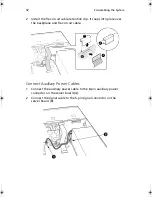
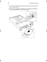
Connect Power Cables
1
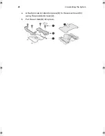
Verify that the P6 backplane power cable is routed from the power
supply to the backplane board and is connected to the white 6-pin
connector.
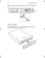
5
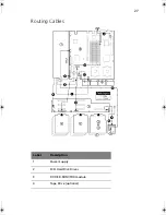
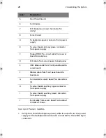
Front Panel Board
6
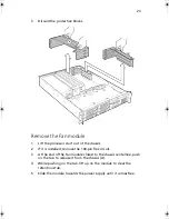
Fan Module
7
SCSI Backplane (shown horizontal for
clarity)
8
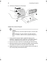
Server Board
A
To backplane power connector from power
supply
B
To server board primary power connector
from power supply
C
Floppy/FP/IDE flex circuit cable from server
board to backplane
D
SCSI cable from server board to backplane
E
USB ribbon cable from front panel board to
server board
F
Ribbon cable from front panel board to
backplane
G
Fan module to server board fan connectors
(2)
H
To server board auxiliary signal connector
from power supply
I
To server board auxiliary power connector
from power supply
J
Serial cable from server board to knockout
on back of chassis
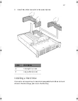
Label
Description
AR700-e.book Page 28 Tuesday, September 10, 2002 2:31 PM
Содержание Altos R700 Series
Страница 1: ...Altos R700 Chassis Subassembly Product guide...
Страница 9: ...1 Chassis Description...
Страница 22: ...1 Chassis Description 14...
Страница 23: ...2 Assembling the System...
Страница 51: ...3 Installing the System in a Rack...
Страница 54: ...3 Installing the System in a Rack 46...
Страница 55: ...4 Working Inside Your Server...
Страница 75: ...Appendix A Equipment Log and Worksheets...
Страница 77: ...69 DAT TApe Drive Item Manufacturer Name and Model Name Serial Number Date Installed...


