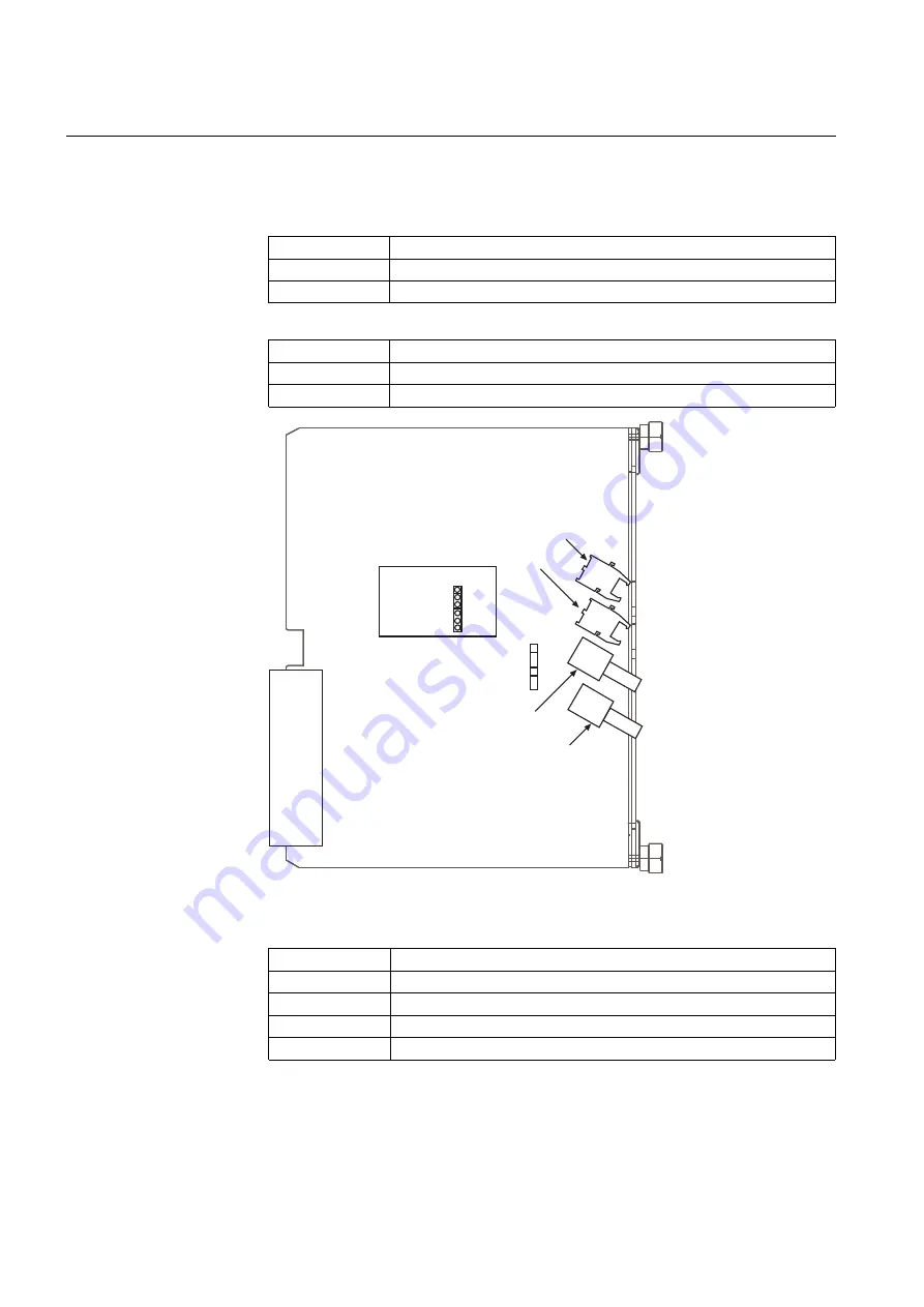
The fibre-optic interface is selected with jumpers X6 and X2 located on the PCB of
the communication module (see Fig. 5.2.2.-2).
Table 5.2.2.-3
Transmitter selection
Transmitter
Position of jumper X6
Plastic
X5.3-TX
Glass
X5.4-TX
Table 5.2.2.-4
Receiver selection
Transmitter
Position of jumper X2
Plastic
X5.3-RX
Glass
X5.4-RX
X6
X2
X5.3
X5.4
TX
TX
X6
X2
X5.3
X5.4
RX
RX
X5.4-RX(glass)
X5.4-TX(glass)
Fibre-optic Interface
X5.3-TX(plastic)
X5.3-RX(plastic)
A040335
Fig. 5.2.2.-2
Jumper location on the communication module for plastic and glass fibre
Table 5.2.2.-5
Fibre-optic rear connectors (plastic and glass)
Terminal
Function
X5.3-TX
Transmitter for plastic fibre
X5.3-RX
Receiver for plastic fibre
X5.4-TX
Transmitter for glass fibre
X5.4-RX
Receiver for plastic fibre
118
REM 610
REM 610
Motor Protection Relay
Technical Reference Manual - ANSI Version
1MRS755537
Содержание REM 610
Страница 1: ...Motor Protection Relay REM 610 REM 610 Technical Reference Manual ANSI Version ...
Страница 2: ......
Страница 6: ...6 ...
Страница 8: ...8 ...
Страница 12: ...12 ...
Страница 124: ...124 ...
Страница 144: ...144 ...
Страница 154: ...154 ...
Страница 157: ......


