


calculated by using a factor 2.5 (instead of the maximum value 4) in order to
reduce the magnitude of the test voltage for the points RE and SE.
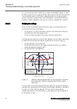
Test sets usually do not have a feature to simulate a real network during a power
swing and apply the related analog quantities at the terminal of the generator. The
scope of the present test is not a simulation of a real network. Voltages and currents
are supplied in order to measure an impedance that changes in the time and
traverses the plane R-X and, in particular, the area inside the lens characteristic.
The test may be performed by applying:
•
Symmetric three-phase voltage at 50 Hz. The magnitude depends on the point
of the characteristic that needs to be verified. The following three main points
of the line segment SE-RE need to be checked:
•
the point RE (R
FwdR
, X
FwdX
)
•
a point which is related to the parameter
ReachZ1
(boundary between
zone 1 and zone 2)
•
the point SE (R
RvsR
, X
RvsX
)
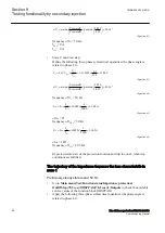
The phase angle of the test voltages is equal to:
•
arctan (
ForwardX
/
ForwardR
) for tests in the quadrant 1 and 2 of the R-X
plane
•
arctan (
ReverseX
/
ReverseR
) -180° for tests in the quadrant 3 and 4 of the R-X
plane
•
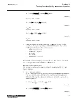
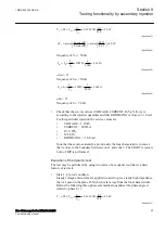
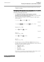
Symmetric three-phase current, where the current is the summation of two
currents that have the same magnitude, but different frequencies.
I
I
A
tf
t
I
50
2
20918
2
10459
=
=
=
=
GUID-F02E8D18-FF87-45BE-8142-E8FA19F6966B V1 EN-US
(Equation 16)
The first current I
50
has frequency 50 Hz, magnitude 10459 A (that is, 1.162 A
secondary) and phase angle 0º.
The second current I
tf
has magnitude 10459 A (that is, 1.162 A secondary),
phase angle 180º (at the starting time of the test) and frequency:
•
49.5 Hz for the test as generator in the quadrant 1 and 2 of the R-X plane
•
50.5 Hz for the test as generator in the quadrant 3 and 4 of the R-X plane
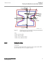
When the trajectory of the impedance, that is seen by the protection
function, traverses the lens characteristic then a pole slipping is
detected. The present procedure avoids tests of points of the line
SE-RE that are too close to the R-axis because in that case the
voltage is close to zero and, therefore, the impedance may approach
a not defined quantity 0/0.
1MRK 506 383-UEN A
Section 9
Testing functionality by secondary injection
Line distance protection REL650 2.2 IEC
85
Commissioning manual
Содержание REL650 series
Страница 1: ...RELION 650 SERIES Line distance protection REL650 Version 2 2 Commissioning manual...
Страница 2: ......
Страница 24: ...18...
Страница 28: ...22...
Страница 38: ...32...
Страница 54: ...48...
Страница 58: ...52...
Страница 178: ...172...
Страница 182: ...176...
Страница 188: ...182...
Страница 196: ...190...
Страница 206: ...200...
Страница 207: ...201...