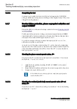
11. Unsymmetrical current detection with CB monitoring: Set measured current
in one phase to 110% of current release level. Activate CLOSECMD and
measure the operating time of the CCPDSC protection.
Use the TRIP signal from the configured binary output to stop the timer.
12. Deactivate the CLOSECMD: Set measured current in one phase to 90% of
Current Release level. Activate CLOSECMD.
NO TRIP signal should appear.
13. Repeat the previous two steps using OPENCMD instead of CLOSECMD.
Asymmetry current detection with CB monitoring: Set all three currents to
110% of Current Release level. Activate CLOSECMD.
NO TRIP signal should appear due to symmetrical condition.
14. Deactivate the CLOSECMD. Decrease one current with 120% of the current
unsymmetrical level compared to the other two phases. Activate
CLOSECMD and measure the operating time of the CCPDSC protection.
Use the TRIP signal from the configured binary output to stop the timer.
15. Deactivate the CLOSECMD. Decrease one current with 80% of the current
unsymmetrical level compared to the other two phases. Activate
CLOSECMD.
NO TRIP signal should appear.
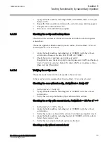
9.4.8.2
Completing the test
SEMOD55625-106 v4
Continue to test another function or end the test by changing the
TESTMODE
setting to
Off
. Restore connections and settings to their original values, if they were
changed for testing purposes.
9.4.9
Voltage-restrained time overcurrent protection VRPVOC
GUID-764DA61A-D987-4358-867A-DA43ADDC6E57 v5
Prepare the IED for verification of settings outlined in Section
.
9.4.9.1
Verifying the settings
GUID-3A2B7FF5-330E-4A0D-AB74-EBAE6258C176 v1
Verifying settings by secondary injection
GUID-39632D30-A8D8-417D-985C-8F886106783E v4
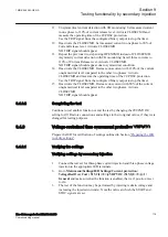
1.
Connect the test set for three-phase current injection and three-phase voltage
injection to the appropriate IED terminals.
2.
Go to
Main menu/Settings/IED Settings/Current protection/
VoltageRestOverCurr ( 51V,2(I>/U<))/VRPVOC (51V,2(I>/U<)):1/
General
and make sure that the function is enabled, that is,
Operation
is set
to
On
.
3.
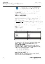
The test of the function may be performed by injecting restrain voltage and
increasing the injected current(s). Note the value at which the START and
STOC signals are set.
1MRK 506 383-UEN A
Section 9
Testing functionality by secondary injection
Line distance protection REL650 2.2 IEC
119
Commissioning manual
Содержание REL650 series
Страница 1: ...RELION 650 SERIES Line distance protection REL650 Version 2 2 Commissioning manual...
Страница 2: ......
Страница 24: ...18...
Страница 28: ...22...
Страница 38: ...32...
Страница 54: ...48...
Страница 58: ...52...
Страница 178: ...172...
Страница 182: ...176...
Страница 188: ...182...
Страница 196: ...190...
Страница 206: ...200...
Страница 207: ...201...


