


If
3 out of 3
currents are chosen for operation: Connect the symmetrical three-
phase injection current into phases L1, L2 and L3.
2.
Connect the test set for the appropriate three-phase voltage injection to the
IED phases L1, L2 and L3. The protection shall be fed with a symmetrical
three-phase voltage.
3.
Block higher set stages when testing lower set stages by following the
procedure described below:
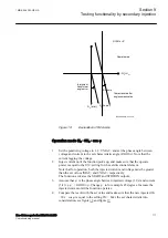
3.1. Set the injected polarizing voltage larger than the set minimum
polarizing voltage (default is 5% of
UBase
) and set the injection current
to lag the appropriate voltage by an angle of about 80° if forward
directional function is selected.
If
1 out of 3
currents are chosen for operation: The voltage angle of
phase L1 is the reference.
If
2 out of 3
currents are chosen for operation: The phase angle of the
phase-to-phase voltage L1L2 is the reference for L1Phase.
If
3 out of 3
currents are chosen for operation: The voltage angle of
phase L1 is the reference.
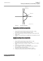
If reverse directional function is selected, set the injection current to lag
the polarizing voltage by an angle equal to 260° (equal to 80° + 180°).
3.2. Increase the injected current, note the operate value of the tested step of
the function and compare it to the set value.
3.3. Decrease the current slowly, note the reset value and compare it to the
reset ratio 95%.
4.
If the test has been performed by injection of current in phase L1, repeat the
test, injecting current into phases L2 and L3 with polarizing voltage
connected to phases L2, respectively L3 (
1 out of 3
currents for operation).
5.
If the test has been performed by injection of current in phases L1 – L2,
repeat the test, injecting current into phases L2 – L3 and L3 – L1 with the
appropriate phase angle of injected currents.
6.
Connect a trip output contact to a timer.
7.
Set the injected current to 200% of the operate level of the tested stage,
switch on the current and check the time delay.
For inverse time curves, check the operate time at a current equal to 110% of
the operate current for
txMin
.
8.
Check that all operate and start contacts operate according to the
configuration (signal matrixes).
9.
Reverse the direction of the injected current and check that the protection
does not operate.
10. If
2 out of 3
or
3 out of 3
currents are chosen for operation: Check that the
function will not operate with current in one phase only.
11. Repeat the above described tests for the higher set stages.
12. Check that start and trip information is stored in the event menu .
Section 9
1MRK 506 383-UEN A
Testing functionality by secondary injection
104
Line distance protection REL650 2.2 IEC
Commissioning manual
Содержание REL650 series
Страница 1: ...RELION 650 SERIES Line distance protection REL650 Version 2 2 Commissioning manual...
Страница 2: ......
Страница 24: ...18...
Страница 28: ...22...
Страница 38: ...32...
Страница 54: ...48...
Страница 58: ...52...
Страница 178: ...172...
Страница 182: ...176...
Страница 188: ...182...
Страница 196: ...190...
Страница 206: ...200...
Страница 207: ...201...


