


8.
Set the injected current to 200% of the operate level of the tested step, switch
on the current and check the time delay.
For inverse time curves, check the operate time at a current equal to 110% of
the operate current in order to test parameter
txmin
.
9.
Check that all operate and start contacts operate according to the
configuration (signal matrixes)
10. Reverse the direction of the injected current and check that the step does not
operate.
11. Check that the protection does not operate when the polarizing voltage is
zero.
12. Repeat the above-described tests for the higher set steps.
13. Finally, check that start and trip information is stored in the event menu.
9.4.5.1
Completing the test
SEMOD53296-122 v4
Continue to test another function or end the test by changing the
TESTMODE
setting to
Off
. Restore connections and settings to their original values, if they were
changed for testing purposes.
9.4.6
Sensitive directional residual overcurrent and power
protection SDEPSDE
SEMOD175060-3 v7
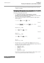
Prepare the IED for verification of settings outlined in Section
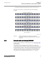
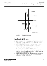
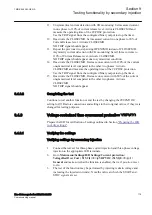
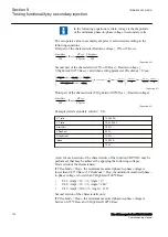
IEC09000021-2-en.vsd
IED test set
NI
IED
NI
L1U
L2U
L3U
NU
U1
U2
U3
NU
TRIP
IEC09000021 V2 EN-US
Figure 17:
Principle connection of the test set
Section 9
1MRK 506 383-UEN A
Testing functionality by secondary injection
108
Line distance protection REL650 2.2 IEC
Commissioning manual
Содержание REL650 series
Страница 1: ...RELION 650 SERIES Line distance protection REL650 Version 2 2 Commissioning manual...
Страница 2: ......
Страница 24: ...18...
Страница 28: ...22...
Страница 38: ...32...
Страница 54: ...48...
Страница 58: ...52...
Страница 178: ...172...
Страница 182: ...176...
Страница 188: ...182...
Страница 196: ...190...
Страница 206: ...200...
Страница 207: ...201...