


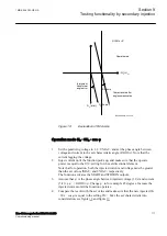


Taking into account the above explanation, inject the voltages related to the
last part of the characteristic and inject a current IL1 200% higher than the set
operation level, and check the trip time delay.
If
tDef_OC
is set to a value different from 0 s, then this time
delay is added to the one that is defined by the IDMT
characteristic.
10. Check the start and operate information that are stored in the event menu.
11. The previous step 8 or 9 may be repeated also for the first and second section
of the characteristic.
12. Supply the IED with symmetric three-phase voltages at their rated values. Go
to
Main menu/Settings/IED Settings/Current protection/
VoltageRestOverCurr(51V,2(I>/U<))/VRPVOC(51V,2(I>/U<)):1/
Undervoltage
and set the setting
Operation_UV
=
On
to activate the
undervoltage stage.
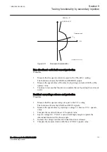
13. Slowly decrease the voltage in two phases simultaneously, until the STUV
and START signals appear.
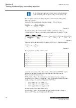
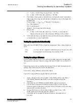
14. Note the operate value. The set operate value in secondary volts is calculated
according to the following equation:
StartVolt
UBase
VT
VTprim
100
3
×
×
sec
IECEQUATION2436 V1 EN-US
(Equation 84)
If the VRPVOC function is used as an overcurrent protection
with undervoltage seal-in, it is necessary to first inject
sufficient current to activate the STOC signal before the
under-voltage step is allowed to operate. In order to achieve
that, apply symmetric three-phase voltages at their rated value
and then inject a current IL1 that is 200% higher than the set
operation level. Then slowly decrease the voltage in two
phases simultaneously, until the STUV and START signals
appear.
15. Increase slowly the applied voltages of the previous two phases and note the
reset value.
16. Check that the trip output of the relay is connected to the input channel of the
test in order to stop the injection and measure the trip time.
17. Inject symmetric three-phase voltages at their rated value and check that the
STUV and START signals reset as well as the trip signals of the function
block (TRIP and TRUV).
18. Instantaneously decrease the voltage in two phases simultaneously to a value
20% lower than the set operate value (take into account the previous note if
VRPVOC is configured in ACT with the undervoltage seal-in feature).
19. Measure the definite time delay for the TRUV and TRIP signals and compare
it with the set value
tDef_UV
.
20. Check that start and operate information is stored in the event menu.
Section 9
1MRK 506 383-UEN A
Testing functionality by secondary injection
122
Line distance protection REL650 2.2 IEC
Commissioning manual
Содержание REL650 series
Страница 1: ...RELION 650 SERIES Line distance protection REL650 Version 2 2 Commissioning manual...
Страница 2: ......
Страница 24: ...18...
Страница 28: ...22...
Страница 38: ...32...
Страница 54: ...48...
Страница 58: ...52...
Страница 178: ...172...
Страница 182: ...176...
Страница 188: ...182...
Страница 196: ...190...
Страница 206: ...200...
Страница 207: ...201...