background image

ABB REL 356 Current Differential Protection

3-26

Settings and Application

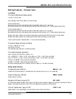
The recommended settings
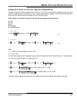
C1 = 0.1
C2 = 0.7
C0 = 0.0

gives the following sensitivity for different faults:

Three phase faults

Phase-phase faults

Single phase to ground faults

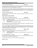
Case 2

When the minimum ground fault current is substantially smaller than the minimum three phase fault current, C0 can be
given a value to increase the sensitivity for ground fault.

The recommended settings
C1 = 0.1
C2 = 0.7
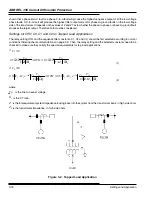
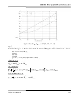
C0 = according to Figure 1
gives the following sensitivity for different faults:

Three phase faults

Phase-phase faults

Single phase to ground faults

The value of C0 is determined from Figure 1. Calculate the ratio I

3

F

min

/I

F

Gmin

 and find this number on the vertical axis.

Find the C0 for the calculated current ratio based on the curve corresponding to the least sensitive fault type.

Selecting C0 is this way results in the same sensitivity for minimum ground fault current as for minimum three phase
fault current.

min

3

min

3

min

1

.

0

1

φ

φ

I

I

C

IT

=

=

min

3

min

3

min

min

60

min

33

.

0

2

3

38

.

0

38

.

0

)

2

1

(

3

1

φ

φ

φφ

φφ

I

I

I

I

e

C

C

IT

j

=

=

=

+

=

±

ο

min

min

min

2

.

0

)

0

2

1

(

3

1

G

G

I

I

C

C

C

IT

φ

φ

=

+

+

=

min

3

min

3

min

1

.

0

1

φ

φ

I

I

C

IT

=

=

min

3

min

3

min

min

60

min

33

.

0

2

3

38

.

0

38

.

0

)

2

1

(

3

1

φ

φ

φφ

φφ

I

I

I

I

e

C

C

IT

j

=

=

=

+

=

±

ο

Содержание REL 356

Страница 1: ...n History Version 1 31 08 29 02 This version includes the following changes from V 1 21 The addition of a settable timer by setting for the channel alarm contact New setting parameter CHAT 0 0 10 0 sec step 0 1 sec The addition of a selectable by setting Transfer Trip Alarm contact New setting parameter GSAL GS TTRP New Voltage Transformer ratio setting The setting range for VTR 300 7000 has been ...

Страница 2: ...t REL356 January 2001 IB 40 226 ABB Automation Inc Substation Automation and Protection Division 7036 Snowdrift Road Allentown PA 18106 USA Tel 610 395 7333 Fax 610 395 1055 This Instruction Book is applicable to the REL 356 Versions 1 21 and all previous versions ...

Страница 3: ...nterface 1 6 56 64 kbps Digital Communication 1 6 Optional Computer Network Interface 1 7 Chassis Dimensions and Weight 1 7 Environmental Data 1 7 CT Requirements for REL 356 Current Differential Protection 1 7 Catalog Information 1 9 Section 2 Installation Operation and Maintenance Introduction 2 1 REL 356 Construction 2 1 REL 356 Modules 2 1 Backplane Module 2 2 Interconnect Module 2 2 Relay Out...

Страница 4: ...ication Channel Testing 2 18 9600 bps Audio Tone Option Only 2 18 56 64 kbps Option Only 2 18 Communication Channel Interface 2 18 Receiver Status 2 18 Transmitter Status 2 18 Routine Visual Inspection 2 19 Acceptance Testing 2 19 Normal Precautions 2 19 Disassembly Procedures 2 19 System Diagrams 2 19 Section 3 Settings and Application Introduction 3 1 Relay System Setup 3 4 Firmware Version VERS...

Страница 5: ...tance XPUD 3 12 Distance Unit Type DTYP 3 12 Positive Sequence Impedance Angle PANG 3 13 Zero Sequence Impedance Angle GANG 3 13 Zero Sequence to Positive Sequence Impedance Ratio ZR 3 13 Backup System Settings Version with Distance Option only 3 13 Backup System Enable BKUP 3 13 Loss of Potential Block LOPB 3 13 Directional Units Settings 3 13 Forward Directional Phase Unit FDOP 3 13 Forward Dire...

Страница 6: ...l Fault Recording Information 3 20 Trigger for Storing Oscillographic Data OSC 3 20 Trigger for Storing Fault Records FDAT 3 20 Ground Trigger Pick Up Level TRGG 3 20 Phase Trigger Pick Up Level TRGP 3 21 Protection System Settings 3 21 Change Detector CD 3 21 Dedicated Direct Transfer Trip DDTT 3 21 Low Set Current Supervision ILTS 3 22 Reclose Block Enable RBEN 3 22 Stub Open Breaker Timer SOBT ...

Страница 7: ... Z2GF 3 31 Zone 2 Reverse Ground Reach Z2GR 3 32 Zone 2 Ground Timer T2G 3 32 Zone 3 Phase Reach Z3P 3 32 Zone 3 Phase Timer T3P 3 32 Zone 3 Forward Ground Reach Z3GF 3 32 Zone 3 Reverse Ground Reach Z3GR 3 32 Zone 3 Ground Timer T3G 3 32 Out of Step Settings Versions with Distance Option only 3 32 Out of Step Trip OST 3 32 Out of Step Block OSB 3 33 Outer Blinder RU 3 33 Out of Step Detection Tim...

Страница 8: ...lay Output Subsystem Test 5 3 Communication Subsystem Test 5 3 9600 bps Audio Tone Option 5 3 56 64 kpbs Digital Communication Option 5 3 Functional Tests Current Differential System 5 4 Single Unit Loopback Test Internal Faults 5 5 Single Unit Loopback Test External Faults 5 8 Dual Unit Back to Back Test External Faults 5 8 Dual Unit Back to Back Test Internal Faults 5 9 Functional Tests Optional...

Страница 9: ...ments 6 1 Connecting Cables 6 1 Modem Communications 6 2 Setting Change Permission and Relay Password 6 2 Password 6 2 Troubleshooting 6 3 Sixteen Fault Target Data 6 3 Digital Fault Recording 6 3 Fault Record Data Definitions 6 4 Analog Signals 6 4 Digital Signals 6 5 Section 7 Glossary Section 8 Application Notes Line Sectionalizing Using a PLC and ABB Protective Relays Modem Communications to A...

Страница 10: ...vs C0 C1 0 1 C2 0 7 3 10 Figure 3 2 Tapped Load Application 3 18 Figure 3 3 Setting Example Tapped Load Application 3 34 Section 4 Measuring Elements and Operational Logic Figure 4 1 IT Filter Output for an A G Fault 4 1 Figure 4 2 Current Differential Logic 4 2 Figure 4 3 Operating Characteristic 4 3 Figure 4 4 Data Frame 4 4 Figure 4 5 Open Breaker Trip 4 5 Figure 4 6 Stub Bus Trip 4 6 Figure 4 ...

Страница 11: ...able 5 8 Zone 3 Phase Ground Forward External Faults Z2GF 7 0 Ohms Z2GR 0 01 Ohms 5 17 Table 5 9 Zone 3 Phase Ground Reverse External Faults Z2GF 7 0 Ohms Z2GR 0 01 Ohms 5 17 Table 5 10 Zone 2 Phase Phase Forward Internal Faults Z2P 4 5 Ohms 5 18 Table 5 11 Zone 2 Phase Phase Forward External Faults Z2P 4 5 Ohms 5 19 Table 5 12 Zone 2 Phase Phase Reverse External Faults Z2P 4 5 Ohms 5 19 Table 5 1...

Страница 12: ... communication for optical fiber or multiplexers modem version for leased telephone lines analog microwave or metallic pilot wires automatic channel delay measurement independent Direct Transfer Trip directional or non directional high set phase and ground independent trip built in optional distance back up REL356 Revision History Main board Version 1 21 10 01 00 Same as v 1 20 except an internal ...

Страница 13: ...v 1 00 with target display improvements Modem version only Version 1 00 08 12 97 Initial release DCI digital communication interface Version 1 10 10 20 98 Improved noise immunity Part number 1614C53G06 Version 1 00 08 12 97 Initial release Part number 1614C53G01 CODEC coder decoder Version 1 12 10 20 98 Improved noise immunity Version 1 10 08 12 97 Initial release Modem module Version 1 10 09 01 0...

Страница 14: ...rrent tripping function is also included in the relaying system The high set overcurrent function activates instantaneous trip when the phase IPH or the ground IGH threshold units detect currents above the settings These units may be supervised by the directional units The phase units are supervised by FDOP Forward Directional Overcurrent Phase and the ground unit is supervised by FDOG Forward Dir...

Страница 15: ... into fault detection Open breaker and stub bus trip Contact outputs for Breaker trip General start Breaker failure initiation Reclose initiate and block System failure alarm Channel failure alarm Trip alarm RS232C series communications port Adaptive protection communication channel delay compensation Digital fault recording 10 analog waveforms from local and remote measurements 64 digital channel...

Страница 16: ...ip Extended contact output with selectable transfer trip contacts Dual power supplies RS232C series communication port with IRIG B input port Modbus PONI Platform Overview The REL 356 relay assembly consists of an outer chassis and an inner chassis which slides into the outer chassis The REL 356 conforms to the following dimensions and weight Height 7 requires 4 rack units 1 75 each 177 mm Width 1...

Страница 17: ...ace DCI are connected to the backplate of the outer chassis The remaining modules are attached to the inner chassis Interconnect module Relay output modules Contact input module Microprocessor module Display module Power supply module Analog input module Modem module for 9600 bps audio tone channel version CODEC coder decoder module for 56 64 kbps digital communication Hardware Structure The basic...

Страница 18: ...at 5 A 32 A rms at 1 A limited by maximum input to the A D converter Thermal 100 x nominal current dc battery voltages nominal range 60 48 Vdc 30 70 Vdc 110 125 Vdc 88 140 Vdc 220 250 Vdc 176 280 Vdc dc burdens normal 15 W tripping 40 W ac burdens volts per phase 0 02 VA at 70 Vac current per phase 0 45 VA at 5 A External connections Terminal blocks located on the rear of the chassis suitable for ...

Страница 19: ...ber optic options Connector ST Wave length 820 nm Cable multi mode Transmitter output into 50 125 mm cable 18 dBm minimum Receiver input 28 dBm minimum Reach typical 2 miles 3 3 km Wave length 1300 nm Cable single mode Transmitter output into 9 125 mm cable Short reach option 20 dB minimum Reach typical 7 5 miles 12 km Medium reach option 10 dB minimum Reach typical 20 miles 32 km Long reach optio...

Страница 20: ... dc 1 minute 3 2 kV dc 1 second Open contacts 1400 V dc continuous Impulse voltage withstand IEC 255 5 1 2 50 ms 0 5 Joule Surge withstand voltage ANSI C37 90 1 IEC 255 22 1 3 kV 1 MHz Fast transient voltage ANSI C37 90 1 IEC 255 22 4 4 kV 10 100 ns EMI field strength withstand ANSI C37 90 2 25 MHz 1 GHz 10 V m Emission tests EN 50081 1 class A Conducted emissions 150 kHz 30 MHz Radiated emissions...

Страница 21: ...nt Even for the most severe saturation a considerably higher amount current of funda mental frequency will be available The above example illustrates the high security of the REL 356 relay It is difficult to derive an exact mathematical formula due to the complexity in mathematically describing CT saturation as a factor of fault current and system dc component One important factor for the amount o...

Страница 22: ...protection Backup protection None P N N Channel interface 9600 bps audiotone British Telecom audiotone 56 64 kbps direct digital 56 64 kbps 820 nm multi mode fiber 56 64 kbps 1300 nm single mode fiber short reach 12 dB 56 64 kbps 1300 nm single mode fiber medium reach 22 dB 56 64 kbps 1300 nm single mode fiber long reach 32 dB A B D H E M L A Test switches FT 14 test switches No switches F N N Rem...

Страница 23: ...ABB REL 356 Current Differential Protection 1 10 Product Overview and Specifications ...

Страница 24: ...hassis and an inner chassis which slides into the outer chassis The REL 356 conforms to the following dimensions and weight Height 7 requires 4 rack units 1 75 each 177 mm Width 19 483 mm Depth 13 6 345 mm Weight 38 Lbs 17 5 kg All of the relay circuitry with the exception of the input isolation transformers and first line surge protection are mounted on the inner chassis to which the front panel ...

Страница 25: ...s electrical connections from and to all other modules from the Backplane at the rear to the Analog Input and Power Supply modules at left and right respectively to the Relay Output and Contact Input modules in the center and to the Modem or CODEC Microproces sor and Display modules at the front of the inner chassis The Interconnect module receives inputs VAG VB G VCG IA IB IC from the Backplane m...

Страница 26: ... two processor systems connected via the Dual Port RAM which perform two main functions Processor 1 samples the analog inputs and provides the operator interface Processor 2 is the protection processor Each processor system P1 and P2 contains the following elements Microprocessor 16 bit microcontroller Intel 80C196 operating at 12 MHz EPROM an ultraviolet erasable read only memory for program stor...

Страница 27: ...ast one of the internal failures shown in the TEST mode The Value Accepted LED flashes once to indicate that a value has been entered successfully The 7 push button switches are used to activate the following functions on the front panel Display Select the LED s to the right of this push button indicate the selected function Reset Function Raise move to the following function Function Lower move t...

Страница 28: ...m transmit level is controlled by the Microprocessor module via the above mentioned parallel bus Modem TXA and RXA are transmitter tone output and receiver tone input lines TXA is 600 ohms and RXA is high impedance TXA will output 5 0 Vdc for 0 dBm modem output Modem receive input is amplified rectified and will output 5 0 Vdc for a 0 dBm input The dc output is approximately proportional to modem ...

Страница 29: ...using multiple A D converter calibration check inputs Failures of the converter trigger alarms b Program Memory Check Sum Immediately upon power up the relay does a complete ROM EPROM checksum of program memory c Power Up RAM Check Immediately upon power up the relay does a complete RAM memory read write tests d Nonvolatile RAM Check All settings and targets are stored in nonvolatile RAM in three ...

Страница 30: ... 14 switch front view All the trip contact outputs are connected to the right side 2FT 14 switch front view Switches 13 and 14 on 2FT 14 may be used for disabling the Breaker Failure Initiation Reclosing Initiation BFI RI control logic The INCOM PONI communication box is mounted thru the Backplate of the outer chassis and connected to the Backplane module An RS 232C serial port is provided for rem...

Страница 31: ... LED is turned OFF if the Relay in service relay has at least one of the internal failures shown in the Test mode The Value Accepted LED flashes only once to indicate that a value has been entered successfully The 5 indicators used for the display selection are Settings Volts Amps Angle LAST FAULT PREVIOUS FAULT Test One of these indicators is always illuminated indicating the mode selected Key Sw...

Страница 32: ... desired value appears If the ENTER key recessed for security purposes is depressed the value which appears in the VALUE field will replace the current value in memory but only if the VALUE ACCEPTED LED flashes once to indicate that the value has been successfully entered into the system For reasons of security a plastic screw is used to cover the ENTER key A wire can be used to lock the plastic s...

Страница 33: ...The following correspondence exists FUNCTION BIT NUMBER Direct Transfer Trip 0 Stub Bus 1 Differential Protection Disable 2 Target Reset 3 52b 4 Not Used 5 Not Used 6 Not Used 7 Function Description STAT SRT Relay Self Check Status Monitor Standing Relay Trip Signal OPTI Display Opto Input Status TRIP BFI SRI 3RI RB GS FALM TALM CALM Relay Test Relay Test Relay Test Relay Test Relay Test Relay Tes...

Страница 34: ...put Test All relay outputs can be tested using the procedure described below 1 Open the FT switch using the red handles of the breaker trip circuits making sure that the following jumper is not disturbed BFI RECLOSE ENABLE 2 Install jumper JMI in position 1 2 on the Microprocessor module 3 Continually depress the DISPLAY key until the TEST LED is illuminated then depress the FUNCTION RAISE or FUNC...

Страница 35: ...tem to its operating state by moving JM1 to position 2 3 on the Microprocessor module and closing the FT switch red handles Self Check The results of the system self check routines are accessible using the following procedure a Continually depress the DISPLAY key until the TEST LED is illuminated then depress the FUNCTION RAISE or FUNCTION LOWER key until the word STAT appears in the FUNCTION FIEL...

Страница 36: ... Test Enable A digital fault record is triggered when the ENTER key is depressed while the TEST mode TEST function is selected on the front panel Standing Relay Trip A real time status monitor of the Standing Relay Trip SRT logic signal is provided as a test mode function The value of the SRT function is YES if any of the trip relays is enabled other wise the value is NO CAUTION The user should ve...

Страница 37: ...r OFF and then ON The computer will allow for a local setting change within 15 minutes Refer to the IL 40 603 Remote Communication Program for detailed information For REL 356 Modbus Communicaton see IL 40 616 Poni M RS485 Product Operated Network Interface User s Guide Digital Fault Recording Refer to ABB Publications IL 40 603 Remote Communication Program IL 40 606 Oscillographic and Recording P...

Страница 38: ...XXX X Amps ÐIC IC metered current angle XXXX deg VCG VCG metered voltage magnitude XXX X volts ÐVCG VCG metered voltage angle XXXX deg 3I0 3I0 metered current magnitude XXX X volts Ð3I0 3I0 metered current angle XXXX deg DATE Date month day MM DD TIME Time hours minutes HH MM SET Setting access status BOTH LOC REM LOP Loss of potential indication YES NO LOI Loss of current indication YES NO OSB Ou...

Страница 39: ...L Differential protection disabled YES NO RIFT Reclose into fault trip YES NO SBT Stub bus trip YES NO OBKT Open breaker trip YES NO OST Out of step trip YES NO TG Time overcurrent ground trip YES NO Z2P Zone 2 phase fault YES NO Z2G Zone 2 ground fault YES NO Z3P Zone 3 phase fault YES NO Notes The YES NO targets are displayed only if they are YES The impedance is dependent upon the CTYP setting ...

Страница 40: ...ult voltage angle XXX X XXX X volts deg IC IC fault voltage magnitude IC fault voltage angle XXX X XXX X amps deg 3I0 3I0 fault voltage magnitude 3I0 fault voltage angle XXX X XXX X volts deg Notes The YES NO targets are displayed only if they are YES The impedance is dependent upon the CTYP setting The internal impedance values are for a 5A ct The impedance value is multiplied by 5 if a 1 A ct is...

Страница 41: ...it ID error TTRP Reception of direct transfer trip code from the remote end DSBL Reception of differential protection disable code from the far end OPBR Reception of open breaker information from the remote relay Transmitter Status The following definitions are used for CHTX NORM Normal state transmission TTRP Transmission of direct transfer trip code to the far end Target Fault Data Information T...

Страница 42: ...not recommended If there is a problem with the REL 356 it should be returned to the factory Disassembly Procedures a Remove the inner chassis from the outer chassis by unscrewing the lockscrew on the front panel and unsnapping the two covers from the FT 14 switches NOTE The inner chassis sub assembly slides in and out of the outer chassis from the front Mating connec tors inside the case eliminate...

Страница 43: ...D PROCESSOR BD DISPLAY BD FT 14 POWER SUPPLY ANALOG INPUT BD FT 14 CONTACT INPUT BD RELAY OUTPUT BDS XFMR INTERCONNECT BD D Digital Comm Interface D CODEC Modem D 56 64 bps Digital Comm Option Only 9600 bps audio Tone Channel Option Only Figure 2 3 Layout of REL 356 Modules Within Inner and Outer Chassis ...

Страница 44: ...ABB REL 356 Current Differential Protection 2 21 Installation Operation and Maintenance Figure 2 4 Block Diagram of REL 356 Relay ...

Страница 45: ... A B C 52 A B C D VA VB VC VN E F G H I J IN IC IB IA 1 2 3 4 6 5 8 7 10 9 TO INPUT FILTERING TB6 REL356 1FT 14 ABB 03 23 97 SW Current differential system using REL356 ABB Automation Inc Substation Automation and Protection Division Allentown PA SIZE FSCM NO DWG NO REV 2097D40 SH 1 OF 3 ...

Страница 46: ...4 M K 2FT 14 VDC BFI1 BFI2 CC CC CC TB2 2 TB2 4 TB5 2 TB5 12 TB5 14 TB4 11 TB4 12 TB4 13 TB4 14 AUDIO TRANSMIT AUDIO RECIEVE TB4 10 TO REMOTE SUBSTATION VIA AUDIOTONE DCI INTERFACE XMIT RCV 2 14 3 16 RS422 DIRECT DIGITAL OR FIBER OPTIC COMMUNICATION NEG POS BFI RECL ENABLE 2FT 14 BFI CONTROL TB1 14 TB1 13 ABB 03 23 97 SW Current differential system using REL356 ABB Automation Inc Substation Automa...

Страница 47: ...097D40 SH 3 OF 3 DTT KEY RYI RI 4 CC CC TB5 9 TB5 7 RYI 2FT 14 N L M K 2FT 14 TB5 10 TB5 8 TARGET RESET TRIP BKR1 TRIP BKR2 TB3 11 TB3 12 RI 3 TB3 9 TB3 10 RI 2 TB3 7 TB3 8 RI 1 TB3 5 TB3 6 RB2 TB3 3 TB3 4 RB1 TB3 1 TB3 2 CHAN AL TB4 7 TB4 8 FAIL AL TB4 5 TB4 6 TA2 TB4 3 TB4 4 TA1 TB4 1 TB4 2 GS TB2 13 TB2 14 BFI2 TB2 3 TB2 4 BFI1 TB2 1 TB2 2 FAIL ALARM CHANNEL ALARM TRIP ALARM RECLOSE BLOCK RECLO...

Страница 48: ... Min Max Step Units Notes Setting Name VERS Software Version 99 99 0 01 XX XX FREQ Rated frequency setting selection Hz 50 60 RP Enable readouts in primary values YES NO CTYP Current transformer type 1A or 5A ct 4 5 1 CTYP In XXXX VTR Voltage transformer ratio 10 7000 300 XXXX OSC Triggering for storing oscillographic data D TRIP ITRG VDI FDAT Triggering for storing fault target data TRIP ITRG TRG...

Страница 49: ...ms BKUP 8 Backup Protection Enable LPBK Loopback Test RLSD dBm 5 Receiver level signal detect setting XMTR dBm 5 Modem transmitter level setting XPUD ohms Primary Ohms per unit DTYP Selection of distance units for XPUD setting PANG deg Positive sequence line impedance angle GANG deg Zero sequence line impedance angle ZR Line impedance ratio Z0L Z1L LOPB 8 Loss of potential blocking selection FDOP ...

Страница 50: ...1 1 0 01 0 01 0 01 0 01 0 01 0 01 0 01 0 01 0 10 ohms cycles cycles cycles cycles year month day hour minute ohms sec ohms ohms sec ohms ohms sec ohms 4 8 3 8 8 8 8 4 8 2 8 4 8 4 8 2 8 4 8 4 8 2 8 8 8 4 8 Inside blinder setting in ohms Note 1 For 5 A relay Setting and step are a factor of 5 lower for 1 A relay Note 3 These settings have a OUT option for disabling a corresponding function Note 4 Th...

Страница 51: ...1200 5 ct is being used Voltage Transformer Ratio VTR This setting is used for the system voltage monitoring if it is selected to be displayed in primary kV It has no effect on the protective system For example Set VTR 575 if 69 000 V to 120 V vt s are being used Digital Fault Recording Information Trigger for Storing Oscillographic Data OSC Indicates trigger for oscillographic data gathering The ...

Страница 52: ... detector is asserted if the absolute difference of present and old sample exceeds 12 5 of the old sample and the difference is larger than 0 1 p u for current and 7 V for voltage The CD can be generated either by using the current change detectors DI or the current and voltage change detectors DVDI The DVDI setting is recommended when the system has voltage inputs and the relay will be used in a ...

Страница 53: ...breaker trip functions When using 52b inputs for the open breaker detection the reset time of the breaker contacts should be carefully considered If the contact reset time is greater than the set SOBT time reclosing will be unsuccessful The reason is as follows after a trip with both breakers open one end closes back into the line successfully The second end closes in but has slow resetting 52b co...

Страница 54: ... single end line charging phase current as measured under balanced conditions all local poles closed and all remote poles open Net line charging current indicates the distributed capacitive current minus any line side shunt reactor current High Set Phase Overcurrent Unit IPH This unit is provided in the REL356 system to supplement the current differential protection by providing a non pilot direct...

Страница 55: ... inrush current will be seen as an external fault and the REL356 relays will remain stable Operating Threshold OTH The operating threshold determines the differential current required for operation according to the formula OTH RES OP 7 0 where OP ITL ITR and RES ITL ITR IT C1I1 C0I0 C2I2 For internal three phase faults IT C1I1 ÐITL ÐITR A 20 margin is recommended i e OTH 0 80 OPmin RESmin 0 80 ITL...

Страница 56: ...lt I3Fmin Case 3 Minimum fault current for a ground fault I FGmin 12 5 of minimum fault current for a three phase fault I3Fmin Case 1 Either C2 or C0 can be used for fault detection of any unsymmetrical fault The use of negative sequence C2 is preferable as the negative sequence currents are more consistent at the two line terminals We therefore recommend to set C0 0 A high value of C2 would incre...

Страница 57: ...ts min 3 min 3 min 1 0 1 φ φ I I C IT Phase phase faults min 3 min 3 min min 60 min 33 0 2 3 38 0 38 0 2 1 3 1 φ φ φφ φφ I I I I e C C IT j ο Single phase to ground faults The value of C0 is determined from Figure 3 1 Calculate the ratio I3Fmin I FGmin and find this number on the vertical axis Find the C0 for the calculated current ratio based on the curve corresponding to the least sensitive faul...

Страница 58: ...ement One terminal should always be set to LEAD and the other to FOLO Local Delay Timer LDT REL 356 uses the LDT setting when no automatic channel delay measurement is being used ALDT NO If fixed channel delay is used LDT should be set to the channel delay displayed in MLDT function of the monitoring functions The LDT setting is used for loop back testing when automatic delay measurement cannot be...

Страница 59: ...o connection to any clock output on the multiplexer is needed For systems using dedicated fiber 850 nm or 1300 nm the setting should be XCLK INT Loopback LPBK This setting should be LPBK NO during normal operation The LPBK setting is only set to YES for testing when the relay is connected in loopback mode i e the communication wires are cross connected so that the relay communicates with itself Lo...

Страница 60: ... backup distance system even though included will be deactivated at all times and will not trip BKUP CT The backup distance system will be activated 150 msec after a CT channel trouble condition occurs It will stay enabled until the channel comes back into service when it will automatically be switched out BKUP CTDD The backup distance system will be activated 150 msec after a CT channel trouble c...

Страница 61: ...ocked as selected by the BKUP setting Zone 2 and Zone 3 Settings Versions with Distance Option only Settings for Zone 2 and Zone 3 protective systems are similar Application of the distance units follow the standard application for a conventional step distance non pilot relaying system Even though they are called Zone 2 and Zone 3 functionally they can serve as one underreaching instantaneous zone...

Страница 62: ...ordinates the Zone 3 reach for phase to phase faults and three phase faults The setting is in secondary ohms Zone 3 Phase Timer T3P Selects the time delay for Zone 3 phase fault detection The setting is in seconds Zone 3 Forward Ground Reach Z3GF This setting controls the forward reach of the Zone 3 ground unit The setting is in secondary ohms Zone 3 Reverse Ground Reach Z3GR This setting controls...

Страница 63: ... of 0 288 ZT or less where ZT is the protected line positive sequence impedance plus the sum of the lowest positive sequence impedance at each end of the line The minimum setting should accommodate a three phase fault resistance value of at least 0 1 ZT ohms based on an arc voltage of 400 volts per foot primary and typical phase separation Using the average of these two conservative figures a reas...

Страница 64: ... The relay energy is affected by two things the sequence network settings and the type of fault The internal faults that produce the lowest network filter output current and the external faults which produces the highest filter output current must regulate the settings If the relay is set to have a negative sequence response the type of internal phase fault that will produce the lowest sequence ne...

Страница 65: ...ad Applications The relay setting OTH and the sequence filter constants C1 C2 and C0 should be first selected according to normal conditions following the recommendations on page 3 9 Then the relay setting and the selected constants need to be checked to make sure they satisfy the special requirements for tap load applications if 0 2 C C T LN C LN R Z Z V C OTH R Z V C 1 1 3 0 2 3 0 1 if 0 2 C C T...

Страница 66: ... channel delay For fault locating and fault recording VT ratio 138000 115 1200 Line length 20 miles Line impedance per mile 0 971 ohms mile primary For distance backup protection Zsec Zprim x CTratio VTratio Zprim x 0 2 Z1L 4 855 79 0 952 j 4 761 ohms primary 0 190 j 4 761 ohms secondary Z0L 9 710 79 1 904 j 9 522 ohms primary 0 381 j 1 904 ohms secondary Z1SLmin 2 56 88 ohms primary local termina...

Страница 67: ...RIP The REL 356 system tripped ITRG The REL 356 system detected the operation of either the TRGP phase or TRGG ground overcurrent elements see below DVDI The voltage and or current change detectors operated The change detectors CD pick up when the current or voltage change between the corresponding data samples spaced one cycle apart exceeds 12 5 minimum 0 5 A or 7 V The use of CD as a trigger of ...

Страница 68: ... sufficient to trigger the change detector Dedicated Direct Transfer Trip DDTT DDTT 0 When the extended output board with additional trip contacts is not included no DDTT setting is available and a received transfer trip signal will always result in closure of the two main trip contacts TRIP 1 and TRIP 2 When the extended output board is included the following setting options are available DDTT 0 ...

Страница 69: ... reclosing will be unsuccessful The reason is as follows after a trip with both breakers open one end closes back into the line successfully The second end closes in but has slow resetting 52b contacts why OPBR open breaker code is still being received by the remote end at the time load current starts to flow The remote end will then trip from the low set IPL elements if OPBK function is used The ...

Страница 70: ... 5 A IPL 1 5 x charging current 1 5 x 0 5 0 75 Þ IPL 1 0 A Net line charging current is defined as the steady state net single end line charging phase current as measured under balanced conditions all local poles closed and all remote poles open Net line charging current indicates the distributed capacitive current minus any line side shunt reactor current High Set Phase Overcurrent Unit IPH IPH 6...

Страница 71: ...nal pickup It can also be set to OUT and no desensitizing on 52b de energization will occur The trip desensitizing characteristic is a linear ramp which multiplies the tripping threshold immediately on de energization of the 52b input to the value to the TDES setting and then slowly over a time period of 30 cycles lowers the trip threshold back to its nominal value Trip desensitizing is not recomm...

Страница 72: ...d be set to a relatively low value We recommend to use C1 0 1 2 8 0 2 min min RES OP OTH 3 0 80 0 2 3 0 8 0 2 8 0 2 1 1 min min I C ITL RES OP OTH currents sequence negative the and sequence positive the sequence zero the are and 2 1 0 2 1 0 2 1 0 I I I where I C I C I C IT C0 and C2 will both multiply fault currents Setting recommendations C1 and C2 for three cases are made Case 1 Minimum fault c...

Страница 73: ...rent faults Three phase faults Phase phase faults Single phase to ground faults The value of C0 is determined from Figure 1 Calculate the ratio I3Fmin I FGmin and find this number on the vertical axis Find the C0 for the calculated current ratio based on the curve corresponding to the least sensitive fault type Selecting C0 is this way results in the same sensitivity for minimum ground fault curre...

Страница 74: ...f minimum three phase fault current C0 should be set to 2 5 The recommended settings C1 0 1 C2 0 7 C0 2 5 gives the following sensitivity for different faults Three phase faults Phase phase faults min 3 min 3 min min 60 min 33 0 2 3 38 0 38 0 2 1 3 1 φ φ φφ φφ I I I I e C C IT j ο Single phase to ground faults min 3 min 3 min 1 0 1 φ φ I I C IT min min min 0 1 0 2 1 3 1 G G I I C C C IT φ φ ...

Страница 75: ...ng eliminates the possibility of connecting two wrong units to each other due to cross connection in the communication channel matrix The UNID numbers in the two units should be adjacent i e 0 in one and 1 in the other 2 in one and 3 in the other 10 in one and 11 in the other The lower value of the pair should always be an even number If UNID 0 in this end set UNID 1 in the remote end Communicatio...

Страница 76: ... This setting defines the minimum threshold for declaring channel trouble CHTB in dBm Fault Locator and Distance System Common Settings Ohms Per Unit Distance XPUD XPUD 0 971 This setting is used by the fault locator algorithm to estimate a calculated distance to the fault The units of XPUD will be in primary ohms per mile or kilometer depending on the setting of DTYP Line impedance per mile 0 971...

Страница 77: ...t affect the differential protection which uses currents only Directional Units Settings Forward Directional Phase Unit FDOP FDOP IN If the system has voltage inputs then the high set phase overcurrent units IPH can be made directional if FDOP is set to IN Forward Directional Ground Unit FDOG FDOG IN If the system has voltage inputs then the high set ground overcurrent unit IPG can be made directi...

Страница 78: ...onditions Zone 3 timers for phase and ground should be set to coordinate with the forward and reverse adjacent high speed trips The timer should include the breaking time of the slowest adjacent breaker plus a tolerance of two to three cycles The characteristic of the distance measuring elements are determined by the settings PANG GANG ZR specified above and the reach settings ZGF ZGR and ZP Groun...

Страница 79: ...setting is in secondary ohms Z3 is used overreaching Minimum recommended setting is 1 2 x ZL1 Þ Z3GF 1 2 x 4 885 x 0 2 1 17 ohms secondary Zone 3 Reverse Ground Reach Z3GR Z3GR 0 29 ohms This setting controls the reverse reach of the Zone 3 ground unit The setting is in secondary ohms Using the same relation as for Z2 Þ Z3GR 0 25 x Z3GF 0 25 x 1 17 0 29 secondary ohms Zone 3 Ground Timer T3G T3G 0...

Страница 80: ... arc voltage of 400 volts per foot primary and typical phase separation Using the average of these two conservative figures a reasonable value to use for the inner blinder resistance is 0 2 ZT RT 0 2 x ZT 0 2 Z1SA Z1SB ZL1 0 2 2 56 2 22 4 86 primary 5 752 x 0 2 secondary 1 15 ohms secondary Outer Blinder RU RU 3 45 ohms This setting is the offset in the perpendicular direction to the line impedanc...

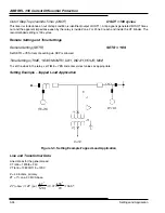
Страница 81: ...he recommended setting is 100 cycles Remote Setting and Time Settings Remote Setting SETR SETR YES Set SETR YES if remote setting via RCP is allowed Time Settings TIME YEAR MONTH DAY WDAY HOUR MIN To set the clock in the relay set TIME YES and enter correct values as appropriate Setting Example Tapped Load Application Figure 3 3 Setting Example Tapped Load Application Line and Transformer Data Lin...

Страница 82: ...H 0 56 A i e use criterion 2 if 0 2 C 1 if 0 2 C 2 where LN V is the line to neutral voltage in primary Volts c R is the CT ratio Z is the total equivalent system impedance looking back into the system from the transformer bank in high side ohms T Z is the transformer impedance in high side ohms OTH e OTH e R Z Z V e C C OTH R Z V e C C j j C T LN j C LN j 46 0 34 2 66 0 3 0 3 240 65 66 08 4 2 138...

Страница 83: ...ABB REL 356 Current Differential Protection 3 36 Settings and Application ...

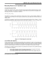
Страница 84: ...phase currents and the second the IT filter output for settings C1 0 1 C2 0 7 and C0 0 0 Figure 4 1 IT Filter Output for an A G Fault Current Differential Algorithm For the comparison process two quantities are generated from the local and remote IT waveforms The operate quantity is derived by vector addition of the local and remote quantities The restraint bias quantity is obtained by adding the ...

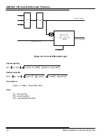
Страница 85: ... RES ITL ITR IF OP 0 7RES OTH THEN trip OTH Im IRL from receiver PLT trip command Figure 4 2 Current Differential Logic Operate quantity 2 2 ITR im ITL im ITR re ITL re ITR ITL OP Restraint quantity 2 2 2 2 ITR im ITR re ITL im ITL re ITR ITL RES Trip decision IF OP 0 7RES OTH THEN TRIP Where ITL local quantity ITR remote quantity OTH set operating threshold ...

Страница 86: ... fault the currents will be practically in phase where OTH should be selected so that minimum internal fault current will produce trip Communication Channel Options REL356 is available with eight different communication interfaces 9600 bps audiotone British Telecom audiotone 56 64 kbps direct digital 56 64 kbps 820 nm multi mode fiber 56 64 kbps 1300 nm single mode fiber short reach 56 64 kbps 130...

Страница 87: ...annel such as leased phone line microwave or metallic pilot wire The modem operates at 9600 bps using Quadrature Ampli tude Modulation QAM at a carrier frequency of 1 700 Hz The transmit level is settable between 1 dBm and 15 dBm Maximum receiver sensitivity is 43 dBm 56 64 kbps Digital Communication Interfaces The digital communication interfaces allow communication via 850 nm multi mode or 1300 ...

Страница 88: ... conditions however the DIDV setting may be preferable Open Breaker Function REL 356 will sense a local open breaker condition by either the 52b contact or by a current sensing element IE or both Note that the minimum setting of IE is 0 04 x In 0 2 A for a 5 A relay why this setting option can not be used on short lines As an Open Breaker logic condition will be set when the current is below the I...

Страница 89: ...se the recloser requires this input instead of RI The RI contacts will close for the following trips Pilot trip from the differential function Stub bus trip Open breaker trip When Reclose Block Enable RBEN is set to Normal Reclose Block NORB the RB contacts will close for the following trips Reclose into fault Trip from the back up system Out of step trip High set overcurrent trip Transfer trip Wh...

Страница 90: ...e is calculated from the voltage and current phasors of the faulted phase s Thus proper faulted phase selection is essential for good fault locator results The distance to the fault is computed by multiplying the imaginary part of the fault impedance times the voltage and current transformer ratios VTR CTR and dividing by the distance multiplier setting XPUD The impedance calculations for the vari...

Страница 91: ...always active if OST is set to WAYI or WAYO The backup distance relaying system includes two zones of a conventional non pilot distance protection Line measurements techniques applies to each zone include Single phase to ground fault detection Three phase fault detection Phase to phase fault detection Phase to phase to ground fault detection Zone 2 and Zone 3 Distance Relaying The optional backup ...

Страница 92: ...ault detection is supervised by IOM the medium set ground overcurrent unit and the ground directional unit FDOG The three phase fault detection is supervised by the phase directional units FDOP and the load restriction blinder RT Each zone has its own timer to coordinate with relays further away for step distance relaying Separate phase and ground timers are provided Single Phase to Ground Single ...

Страница 93: ... fault detection is accomplished by the logic operation of one of the three ground units plus the 3FF output from the phase selector However for a three phase fault condition the computation of the distance units will be OP VXG IX ZP REF VQ Where VQ VCB for phase A VAC for phase B VBA for phase C VXG VAG VBG or VCG IX IA IB or IC ZP zone reach setting in secondary ohms ...

Страница 94: ... 9 Mho Characteristic for Three Phase Faults Phase to Phase The phase to phase unit responds to all forward phase to phase faults and some phase to phase to ground faults The operating and reference quantities are OP VAB IAB ZP REF VCB ICB ZP Figure 4 10 Mho Characteristic for Phase to Phase Faults ...

Страница 95: ...r setting RU and BI inner blinder setting RT and are parallel to the line impedance setting i e they are tilted by the PANG phase angle setting Figure 4 11 Blinders for the Out of Step Logic The RU and RT settings are the distance perpendicular to the line positive sequence impedance that the blinders are displaced from the latter The RT setting is also for load restriction and if any three phase ...

Страница 96: ...ep override timer that bypasses OSB after it has timed out and lets the relay trip Loss of Potential LOPB Loss of potential logic is used to supervise the distance measurements in the distance backup system When this condition exists all impedance measuring units well have their output blocked The V0 x notI0 logic will detect one or two blown fuses but will fail to detect the unlikely simultaneous...

Страница 97: ...IBCD VBCD VB IC PHASE C ICL ICE ICH ICCD VCCD VC 3I0 IGL IGH IGCD IC IT IB IA SYMM COMP FILTER C0 C1 C2 IT LBPD LDPD 52b TARGET RESET SBP INPUTS ROBR REMOTE OPEN BREAKER VFRI IT CURRENT FROM REMOTE END RDTT RECEIVED DIRECT TRANSFER TRIP RDPD REMOTE DIFF PROT DISABLED FEPH FRAME ERRORS PER HOUR COMM XMTR CHOK DISABLE 0 200 VFLI LDTT SBP OPBR RY2 RY1 L L BK1 BK2 BFI1 BFI2 0 50 TRIPA BFIA T1DAND T2DA...

Страница 98: ...MOTE END VFRI 90 deg DELAY OPERATE FUNCTION RESTRAINT FUNCTION VFRR OP RES OP 0 7RES OTH DPT CURRENT DIFFERENTIAL TRIP ALGORITHM MOTH OTH x TDES TO OTH RAMPED OVER 20 CYCLES AFTER BREAKER CLOSES MOTH OTH MOTH IT DFT COSINE FILTER 52b 32 CYCL OTH TDES FDOPA FDOPB FDOPC FDOPA FDOPB FDOPC FDOP3F PHASE DIRECTIONAL ELEMENTS D2 D0 DIRU NSEQ ZSEQ FDOG GROUND DIRECTIONAL ELEMENTS GDM GOOD CHANNEL DELAY ME...

Страница 99: ...DOPB FDOPC FDOP3F PHASE DIRECTIONAL ELEMENTS 3F Z2 3F OSB Z2 21BI FDOP3F IL3F F AGZ2 F BGZ2 F CGZ2 2F G IOM FDOG Z2 2F G Z2G FF Z2 FF 3F Z2P SEBR IL LOPB T2P BLK T2P T2P 0 Z2PT TRSL Q Q SET CLR S R Z2P LOPB IOM SEBR FDOG F G T2G BLK T2G T2G 0 Z2GT TRSL Q Q SET CLR S R Z2G 3F Z3 3F OSB Z3 21BI FDOP3F IL3F F AGZ3 F BGZ3 F CGZ3 2F G IOM FDOG Z3 2F G Z3G FF Z3 FF 3F Z3P SEBR IL LOPB T3P BLK T3P T3P 0 ...

Страница 100: ...rimary and secondary dc power Consult the relay name plate for rated voltage NOTE Before turning on dc power check jumper positions on the Contact Input and Microprocessor modules Analog Input and Front Panel Metering Test STEP 1 Turn on the primary and optional secondary dc input power if used Make sure that the FREQ setting matches the line frequency and the RP setting is set to NO Readout in se...

Страница 101: ...ltiplied by the CT ratio CTR Contact Input Subsystem Test Make sure that the input voltage selection jumpers on the contact input module correspond to the desired contact wetting voltage as specified in Section 2 Contact Input Module Apply the rated voltage across the terminals shown in the table below Using procedure described in Section 2 Contact Input Test verify proper response of the front pa...

Страница 102: ...SPLAY SELECT key on REL 356 front panel several times to select the VOLTS AMPS ANGLE mode Use the FUNCTION RAISE LOWER keys to display the XMTR monitoring function The transmitter output level is measured via the XMTR monitoring function should read between 2 an 5 dBm Change the XMTR setting to 11 dBm The transmitter output level as measured via the XMTR monitoring function should read between 8 a...

Страница 103: ... 1 2 is de energized Change the OPBR setting to 52B to disable the open breaker code transmission Change the ALDT setting to NO since automatic delay time measurement is not possible with communication channel in a Loopback configuration Turn the dc supply connected to the REL 350 s dc Battery inputs off for 1 second then back on again to re initialize the modem s ALDT setting on power up sequence...

Страница 104: ...msec for 56 64 kbs communication channel Modem version A or T is shown in the style number STEP 2 Power down the unit STEP 3 Make the connections on the reat of the REL 356 that correspond to the type of communication channel that you have as specified in Communication Subsystem Test above Freq 60 Z2GR 2 0 RP NO CTYP 5 CTR 5000 VTR 7000 OSC TRIP FDAT TRIP TRGG 0 5 TRGP 0 5 CD DI ILTS OUT RBEN NORD...

Страница 105: ...different cases are presented only one needs to be performed REL 356 Test Tables V 1 20 The measuring error is 10 of calculated pick up value or 0 250 A whichever is greater Test Conditions Case 1 C0 0 C1 0 1 C2 0 7 OTH 0 50 OTH 0 70 for V1 15 or lower Test Table 1 Fault Type I Amps Ð Angle Calculated Pickup Value Current Pickup range AG IA 4 17Ð 0 IB 0 Ð 120 IC 0 Ð 240 4 17A 3 15 4 59A BG IA 0 Ð ...

Страница 106: ... 1 55 2 05A CA IA 2 20Ð 60 IB 0 Ð 120 IC 2 20Ð 240 2 20A 1 95 2 45A ABC IA 8 33Ð 0 IB 8 33 Ð 120 IC 8 33 Ð 240 8 83A 7 50 9 16A Test Conditions Case 3 C0 2 5 C1 0 1 C2 0 7 OTH 0 50 OTH 0 70 for V1 15 or lower Test Table 3 Fault Type I Amps Ð Angle Calculated Pickup Value Current Pickup range AG IA 0 81Ð 0 IB 0 Ð 120 IC 0 Ð 240 0 81A 0 56 1 06A BG IA 0 Ð 0 IB 1 08Ð 120 IC 0 Ð 240 1 08A 0 83 1 33A C...

Страница 107: ...gender so the cable needs to be female gender on both ends Connections are as follows Pin 2 tp pin 3 TXA to RXA Pin 3 to pin 2 RXA to TXA Pin 14 to pin 16 TXB to RXB Pin 16 to pin 14 RXB to TXB 56 64 kbps Fiber Optic Option The Fiber optic option requires a fiber optic cable with an in line attenuator be placed between the XMIT connector of Unit 1 s DCI to the RCVR connector of Unit 2 s DCI The sa...

Страница 108: ...greater than those shown in Tables 5 1 5 2 5 3 and verify that the relay does not trip on external faults Dual Unit Back to Back Test Internal Faults To simulate an internal fault reverse the CT polarity on unit number 2 Test the relay per Tables 5 1 5 2 5 3 by applying faults and verifying that the relay trips Internal Fault s Current connections IA IAR IB IBR IC ICR TB6 6 TB6 5 TB6 8 TB6 7 TB6 1...

Страница 109: ... Ground Units To calculate the fault impedance seen by the relay system the following formula applies Where x is either phase a b or c The above formula is rigorous and general However if a quick approximation of the minimum trip current required at different angles q is desired the following formula applies Z2GF PANG q 1 ZR 1 3 cos VXG lxg where x is either phase a b or c Zone 2 Phase Ground Elem...

Страница 110: ...Ð 0 Ia 0 4 05 Ð 75 Vb 30 Ð 120 240 Ib 4 4 Ð 195 165 Vc 69 Ð 240 120 Ic 0 Z2T Trip Fault type BG Z2G Unit Trip time 100 132 ms BG at MTA 45 90 of reach fault Va 69 Ð 0 Ia 0 2 86 Ð 30 Vb 30 Ð 120 240 Ib 6 23 Ð 150 210 Vc 69 Ð 240 120 Ic 0 Z2T Trip Fault type BG Z2G Unit Trip time 100 132 ms BG at MTA 45 90 of reach fault Va 69 Ð 0 Ia 0 2 86 Ð 120 Vb 30 Ð 120 240 Ib 6 23 Ð 240 120 Vc 69 Ð 240 120 Ic ...

Страница 111: ...a 5 09 Ð 30 330 3 5 Ð 30 Vb 69 Ð 120 240 Ib 0 Vc 69 Ð 240 120 Ic 0 No Trips AG at MTA 45 110 of reach fault Va 30 Ð 0 Ia 5 09 Ð 120 240 3 5 Ð 120 Vb 69 Ð 120 240 Ib 0 Vc 69 Ð 240 120 Ic 0 No Trips BG at MTA 110 of reach fault Va 69 Ð 0 Ia 0 4 95 Ð 75 Vb 30 Ð 120 240 Ib 5 09 Ð 195 165 Vc 69 Ð 240 120 Ic 0 No Trips BG at MTA 45 110 of reach fault Va 69 Ð 0 Ia 0 3 5 Ð 30 Vb 30 Ð 120 240 Ib 5 09 Ð 150...

Страница 112: ...c 0 No trips BG at MTA 180 50 of reach fault Va 69 0 Ia 0 2 25 105 Vb 30 120 240 Ib 8 15 345 Vc 69 240 120 Ic 0 No trips CG at MTA 180 50 of reach fault Va 69 0 Ia 0 2 25 105 Vb 69 120 240 Ib 0 Vc 30 240 120 Ic 8 135 225 No trips Zone 2 Phase Ground Element With Reverse Reach NOTE Change the Z2GR distance setting to 4 5 ohms before applying the following faults in Tables 5 4 5 5 and 5 6 to the rel...

Страница 113: ...TA 45 90 of reach fault Va 69 0 Ia 0 4 05 30 Vb 30 120 240 Ib 4 4 150 210 Vc 69 240 120 Ic 0 Z2T Trip Fault type BG Z2G Unit Trip time 100 132 ms BG at MTA 45 90 of reach fault Va 69 0 Ia 0 4 05 120 Vb 30 120 240 Ib 4 4 240 120 Vc 69 240 120 Ic 0 Z2T Trip Fault type BG Z2G Unit Trip time 100 132 ms CG at MTA 90 of reach fault Va 69 0 Ia 0 4 05 75 Vb 69 120 240 Ib 0 Vc 30 240 120 Ic 4 4 315 45 Z2T ...

Страница 114: ...of reach fault Va 30 0 Ia 3 6 30 330 4 95 30 Vb 69 120 240 Ib 0 Vc 69 240 120 Ic 0 No trips AG at MTA 45 110 of reach fault Va 30 0 Ia 3 6 120 240 4 95 120 Vb 69 120 240 Ib 0 Vc 69 240 120 Ic 0 No trips BG at MTA 110 of reach fault Va 69 0 Ia 0 4 95 75 Vb 30 120 240 Ib 3 6 195 165 Vc 69 240 120 Ic 0 No trips BG at MTA 45 110 of reach fault Va 69 0 Ia 0 4 95 30 Vb 30 120 240 Ib 3 6 150 210 Vc 69 24...

Страница 115: ...h NOTE Change the T3G timer setting to 1 0 seconds before applying the faults in Tables 5 7 5 8 and 5 9 7 Forward Internal Faults For forward Zone 3 Phase Ground Internal faults use the Table 5 7 of voltages and currents In each case apply the 3 phase voltage to the relay system first then suddenly apply the currents listed Compare the relay system trip target data to the applied fault values The ...

Страница 116: ... 120 Ic 0 No trips CG at MTA 110 of reach fault Va 69 0 Ia 0 7 7 75 Vb 69 120 240 Ib 0 Vc 25 240 120 Ic 1 95 315 45 No trips 9 Reverse External Faults For reverse Zone 3 Phase Ground External faults use the Table 5 9 of voltages and currents In each case apply the 3 phase voltage to the relay system first then suddenly apply the currents listed In each case the relay system should not trip as thes...

Страница 117: ...uddenly apply the currents listed Compare the relay system trip target data to the applied fault values The target data should be within 10 on magnitude and 3 degrees on phase Trip time should fall within 100 132 milliseconds Table 5 10 Zone 2 Phase Phase Forward Internal Faults Z2P 4 5 Ohms Volts Angle I Amps Angle Fault Z Ohms Angle Relay System Operation AB at MTA 90 of reach fault Va 17 3 0 Ia...

Страница 118: ...ips CA at MTA 110 of reach fault Va 17 3 0 Ia 3 03 105 255 4 95 75 Vb 69 120 240 Ib 0 Vc 17 3 240 120 Ic 3 03 285 75 No Trips 12 Reverse External Faults For reverse Zone 2 Phase Phase External faults use the Table 5 12 of voltages and currents In each case apply the 3 phase voltage to the relay system first then suddenly apply the currents listed In each case the relay system should not trip as th...

Страница 119: ...ault Va 69 0 Ia 0 6 3 75 Vb 1 73 120 240 Ib 2 38 165 195 Vc 1 73 240 120 Ic 2 38 345 15 Z3T Trip Fault type BC Z3P Unit Trip time 1 0 1 05 mS CA at MTA 90 of reach fault Va 17 3 0 Ia 2 38 105 255 6 3 75 Vb 69 120 240 Ib 0 Vc 17 3 240 120 Ic 2 38 285 75 Z3T Trip Fault type CA Z3P Unit Trip time 1 0 1 05 mS 14 Forward External Faults For forward Zone 3 Phase Phase External faults use the Table 5 14 ...

Страница 120: ...fault Va 17 3 0 Ia 4 28 225 135 3 5 105 Vb 17 3 120 240 Ib 4 28 45 315 Vc 69 240 120 Ic 0 No Trips BC at MTA 180 50 of reach fault Va 69 0 Ia 0 3 5 105 Vb 1 73 120 240 Ib 4 28 345 15 Vc 1 73 240 120 Ic 4 28 165 195 No Trips CA at MTA 180 50 of reach fault Va 17 3 0 Ia 4 28 285 75 3 55 105 Vb 69 120 240 Ib 0 Vc 17 3 240 120 Ic 4 28 105 255 No Trips 3 Phase Units To calculate the fault impedance see...

Страница 121: ...r forward Zone 2 Three Phase External faults use the Table 5 17 of voltages and currents In each case apply the 3 phase voltage to the relay system first then suddenly apply the currents listed The relay system should not trip as these faults are beyond the reach of the Zone 2 Three Phase units Table 5 17 Zone 2 Three Phase Forward External Faults Z2P 4 5 Ohms Volts Angle I Amps Angle Fault Z Ohms...

Страница 122: ...nd currents In each case apply the 3 phase voltage to the relay system first then suddenly apply the currents listed The relay system should not trip as these faults are beyond the reach of the Zone 3 Three Phase units Table 5 20 Zone 3 Three Phase Forward External Faults Z3P 7 0 Ohms Volts Angle I Amps Angle Fault Z Ohms Angle Relay System Operation BC at MTA 110 of reach fault Va 20 0 Ia 2 6 75 ...

Страница 123: ...e tests are optional and require programing Computer Aided Multi amp or Doble test equipment In the R X diagram the positions shown correspond to the following quantities PANG 65 GANG 65 ZR 3 0 BKUP OUT LOPB NO FDOP IN FDOG IN DIRU ZSEQ IOM 0 5 TOG BLK Z2P 8 5 T2P 0 1 Z2GF 6 5 Z2GR 0 01 T2G 0 1 Z3P 11 0 T3P 2 Z3GF 11 0 Z3GR 0 01 T3G 2 OST WAYO OSB BOTH RT 2 0 RU 4 0 OST1 2 OST2 3 OST3 3 OSOT 100 1...

Страница 124: ...e measured should be 10 6 Ð 105 ohms V Volts I Amps 1 Va 69 Ð0 Vb 69 Ð 120 Vc 69 Ð 120 Ia 5 Ð 5 Ib 5Ð 125 Ic 5Ð 115 2 Va 20 Ð0 Vb 20 Ð 120 Vc 20 Ð 120 Ia 4 5 Ð 25 Ib 4 5Ð 145 Ic 4 5Ð 95 3 Va 20 Ð0 Vb 20 Ð 120 Vc 20 Ð 120 Ia 6 Ð 65 Ib 6Ð 175 Ic 6Ð 55 4 Va 20 Ð0 Vb 20 Ð 120 Vc 20 Ð 120 Ia 4 Ð 100 Ib 4Ð 140 Ic 4Ð 20 5 Va 69 Ð0 Vb 69 Ð 120 Vc 69 Ð 120 Ia 6 5 Ð 105 Ib 6 5Ð 135 Ic 6 5Ð 15 POS Z app 21 B...

Страница 125: ...ive Sequence or V1 Small quantities of V2 V0 are acceptable and are a result of small phase unbalalnces in the system and or variations in the PT s themselves Verify at both ends and record the data STEP 5 Close the breaker in at the remote end STEP 6 Verify that the current levels and angles displayed in the metering display correspond to what is actually flowing in the system This is more easily...

Страница 126: ...sc Data File enter Select REL 356 enter Find the os6 file you saved in step 3 enter Wait for the OSCAR program to calculate the analog and digital data in the saved file Select Graph Osc Data enter STEP 5 Now you will see the analog and digital data associated with this record Press F1 ANA MENU Press F3 SELECT MOVE DN Press F8 REMOVE TRACE and repeat until OP and RES are the two top traces on the ...

Страница 127: ...ABB REL 356 Current Differential Protection 5 28 Testing ...

Страница 128: ...e communication data rate This port option is always black in color can be set for speeds of 300 1200 2400 4800 9600 or 19200 bps and offers an option for IRIG B time clock synchronization input The third style is a PONI M Modbus RS485 Product Operated Network Interface for connecting the REL 356 system to a Modbus Host Communication details for this option are given in IL 40 616 Personal Computer...

Страница 129: ...munication to ABB Relays provides a step by step guide for the remote communi cations setup Setting Change Permission and Relay Password To gain access to certain communication port functions the REL 356 must have the remote setting capability permis sion SETR set to YES and knowledge of the relay password is required All communications port functions listed below require SETR set to YES before th...

Страница 130: ...r complete 16 fault data the computer communication is necessary Digital Fault Recording Three digital fault records are stored in REL 356 Each set includes seven analog traces Va Vb Vc Ia Ib Ic and In with one cycle pre fault and 7 cycle fault information and 64 digital signals based on 12 samples per cycle NOTE IF POWER IS INTERRUPTED TO RELAY ALL OSCILLOGRAPHIC DATA WILL BE LOST Table 6 1 Commu...

Страница 131: ...main menu offers the following display files for REL 356 Analog Signals The following signals are displayed on the main OSCAR screen following a download of both analog and digital signals from the REL 356 relay la phase A current lb phase B current lc phase C current 3I0 zero sequence current note the negative sing Vag phase A to ground voltage Vbg phase B to ground voltage Vcg phase C to ground ...

Страница 132: ...nals are easiest identified by finding them in the SYSTEM LOGIC diagrams at the back of this IL The first 20 digital signals are display in the OSCAR main screen after downloading the file from the REL 356 relay The command F8 DIG MENU displays 20 additional signals and the command F1 SCROLL DIGI UP displays the remain ing 24 signals one by one Main Screen PLT pilot trip SBT stub bus trip OBKT ope...

Страница 133: ...lure alarm ALMT trip alarm ALMC channel alarm SEBR enable backup system RIFT reclose into fault PT na PTG na TG FDOG timer Z2P zone 2 phase distance Z2G zone 2 ground distance Z3P zone 3 phase distance Z3G zone 3 ground distance ECHO na IOM medium set ground overcurrent element LOP loss of potential block LOI loss of current 21BI inner blinder OSB out of step block TGTP time delayed ground trip T2...

Страница 134: ...nt flowed BK5 Breaker current flowed BK6 Breaker current flowed BKUP Back up setting C0 Zero sequence setting parameter C1 Positive sequence setting parameter C2 Negative sequence setting parameter CA Fault type C A CD Change detector CG Fault type C G CHRX Channel receive status CHTB Channel trouble CHTX Transmitter status CODEC Coder Decoder CT Current transformer CTDD Back up system setting CTR...

Страница 135: ...t IGH High set ground overcurrent IGL Low set ground overcurrent unit ILTS IL trip supervision IOM Medium set ground overcurrent unit IPH High set phase overcurrent IPL Low set phase overcurrent unit IT Composite current ITL Local filtered composite current ITR Remote composite current KBPS Communication speed LDFL Lead follower mode LDT Local delay timer LEAD Lead mode LED Light emitting diode LO...

Страница 136: ...tor ROM Read only memory RP Enable readouts in primary values RT Inner blinder setting load restriction RU Outer blinder setting S N ratio Signal to noise ratio SET Setting access status SETR Remote setting SLGF Single line to ground fault SNR Signal to noise ratio T2G Zone 2 ground timer T2P Zone 2 phase timer T3G Zone 3 ground timer T3P Zone 3 phase timer TDES Trip desensitizing TG Time overcurr...

Страница 137: ... sequence line impedance Z2GF Zone 2 ground forward Z2GR Zone 2 ground reverse Z2P Zone 2 phase Z3G Zone 3 ground Z3GF Zone 3 ground forward Z3GR Zone 3 ground reverse Z3P Zone 3 phase ZFG Forward zone reach setting ZGF Forward ground impedance reach ZGR Reverse ground impedance reach ZP Forward phase impedance setting ZR Zero sequence to positive sequence impedance ratio 3 12 3 12 3 12 2 16 4 9 4...

Страница 138: ...cation 2 Modbus via Radio IED Receiving PCD 2000 Feeder Location 3 THE CLOUD TPU 2000R Substation Location 1 TPU 2000R Feeder Location 3 DPU 2000R Substation Location 2 Figure 1 Typical PLC Protective Relay Report by Exception Application The scenario illustrated is indicative of a line sectionalizing load shedding installation Using intelligent off the shelf IEDs such as protective relays and PC ...

Страница 139: ...ions made by the PLC or manually via an operator at the HMI station 3 The PLC reads writes information between itself and the PCD2000 Data gathered by the PLC is Breaker Status 52a 52b is read Cumulative Watts per phase and 3 phase Vars per phase and 3 phase Amps Volts frequency values are read Control Operation capabilities such as breaker trip and breaker close can be completed automatically via...

Страница 140: ... execute the MAGELIS HMI will display an error message as to the cause of failure in the restoration process MANUAL MODE disables the PLC s capability to trip close the breaker The PLC still computes the loading values and alerts the operator as to alarms The PLC also communicates with MAGELIS MMI and displays messages breaker status information metering data informing the operator if adequate loa...

Страница 141: ...the specific vendor s PLC allow computations to occur Compact PLC Segment 1 Compact PLC reads ABB DPU 2000R via Modbus Plus Path A The Compact PLC reads 1 New Alarm Status 2 Currents 3 Voltages 4 Power 5 Status The Compact PLC can perform MANUAL or AUTOMATIC CONTROL 1 TRIP 2 RESET TARGETS 3 RESET ALARMS 4 RESET LATCHES The Compact PLC serves as a data concentrator Path A Modbus Plus Network TPU 20...

Страница 142: ...TATUS VALUES REGISTERS 41727 THRU 41736 WRITE TPU EXECUITE INSTRUCTION REG 41410 WRITE TPU TRIP SETUP INSTRUCTIONS REGS 41411 41415 WRITE TPU RESET TARGET INSTRUCTIONS REGS 41411 41415 WRITE TPU RESET ALARM INSTRUCTIONS REGS 41411 41415 WRITE TPU RESET STATUS INSTRUCTIONS REGS 41411 41415 PTR 6 PTR 7 PTR 8 PTR 9 PTR 10 Paired Instruction Write index one index 7 10 first then Ptr 6 last to execute ...

Страница 143: ...hen cyclic polling resumes and this logic construct is energized NETWORK 3 Figure 6 As illustrated in Figure 3 all instruction parameterization registers for the MSTR instruction is stored in the compact 6X memory registers This network instruction upon a change of the CTR instruction s cyclic poll reads the block in 6X memory and places it in 4X memory The contents are then moved into the MSTR bl...

Страница 144: ...ritten at any one time the program has been limited to Modbus Plus data accesses of 30 registers to conserve PLC memory The data is stored in 4X memory 40110 through 40149 Figure 7 Segment 1 Network 4 Master Polling Block NETWORK 5 Figure 8 The UCTR in this network counts the BAD Modbus Plus network transfers an excellent indicator for network troubleshooting and program troubleshooting This netwo...

Страница 145: ...ndicator for the program that the FIFO has an entry and the master should be halted Figure 9 FIFO MSTR Halt Logic NETWORK 7 Figure 10 This network delays the initiation of the MSTR block send instructions when a FIFO command has been sensed in the buffer The pointer to this command is in the 40163 pointer register The delay is 100 mS As can be seen in the ladder logic the FOUT FIFO out stack is po...

Страница 146: ...sters read written 60XXXX 2 Address in TPU to be read written 60XXXX 3 Node Route 1 Address 60XXXX 4 Node Route 2 Address 60XXXX 5 Node Route 3 Address Routing address Paths 5 and 4 are a value of 0 FILE 2 6X registers are the data written to the TPU Each command is in a block of 10 If the command in the corresponding block is 1 read then the file 2 block of registers is a don t care If the comman...

Страница 147: ...er is a WRITE instruction then the pointer placed in the buffer is multiplied by 10 to get the block of data to transfer to the MSTR data register buffer 40110 The multiplier for instructions are PTR 1 Block 0 Add 0 to pointer for FILE 2 60000 PTR 2 Block 1 Add 10 o pointer for FILE 2 60010 PTR 3 Block 2 Add 20 pointer for FILE 2 60020 PTR 4 Block 3 Add 30 to pointer for FILE 2 60030 PTR 5 Block 4...

Страница 148: ...DATA REG 40513 40518 VOLTAGE ANGLE DATA REG 40528 40533 POWER VALUES REG 41153 41156 ALARM STATUS VALUES The Command 6 is the trigger command for all the WRITE commands which include TRIP COMMAND Write 41411 41415 and WRITE 41410 RESET TARGETS Write 41411 41415 and WRITE 41410 RESET ALARMS Write 41411 41415 and WRITE 41410 RESET LATCHED DATA Write 41411 41415 and WRITE 41410 The commands as illust...

Страница 149: ...NALIZING USING A PLC AND ABB PROTECTIVE RELAY Page 12 of 53 Figure 15 TPU Read Currents FIFO Pointer Load Logic Figure 16 TPU Read Voltage FIFO Pointer Load Logic Figure 17 TPU Read Wattage FIFO Pointer Load Logic ...

Страница 150: ...LIZING USING A PLC AND ABB PROTECTIVE RELAY Page 13 of 53 Figure 18 TPU Read Alarm Status FIFO Pointer Load Logic Figure 19 TPU Trip Breaker FIFO Pointers Load Logic Figure 20 Reset Targets FIFO Pointers Load Logic ...

Страница 151: ...etrieval from the PLC The PLC then serves as a data concentrator The TPU data registers are contained in 41700 through 41726 The ladder logic networks in this construct are triggered when the MSTR instruction has obtained the information from the relay The instruction then transfers the appropriate quantity to the appropriate registers as illustrated by Figure 3 above The SUB instruction determine...

Страница 152: ...ELAY Page 15 of 53 Figure 23 Read in Reply to Status Data Request and Store in PLC Registers Figure 24 Read in Reply to Phase Current Data Request and Store in PLC Registers Figure 25 Read in Reply to Phase Voltage Data Request and Store in PLC Registers ...

Страница 153: ...ia a 10 bit protocol The SCATTER RADIO MODEMS have the advantage that no special licensing is required for connection to the devices The ladder logic required for data retrieval is located in the ladder logic segment 2 and is based upon the XMIT instruction which turns the PLC s RS232 port into a MODBUS master This enables the PLC to query attached devices and poll for data In this way the PLC is ...

Страница 154: ...l be reviewed for the method to complete the data exchange between the PLC and the IED s SEGMENT 3 NETWORK 1 The FIFO used to gather the information from the IED s is reset whenever data is transferred into the FIFO for polled queue This is a standard instruction construct which is similar to that used for the MSTR instruction Figure 29 Segment 3 Network 1 FIFO Entry for XMIT Instruction Notificat...

Страница 155: ...ata The XMIT instructions are stored in FILE 2 and FILE 1 of 6X memory beginning at addresses 600500 and 610500 respectively File 1 parameterizes the XMIT block parameters and FILE 2 parameterizes the particular MODBUS request The mathematics of this block calculates the data in the following way FILE 1 POINTER Reg 40334 Pointer Reg 40331 10 500 offset FILE 2 POINTER REG 30337 Pointer Reg 40331 30...

Страница 156: ...ad Written 40357 DPU or PCD Address 40358 DPU PCD Data Address to Read or Write 40359 0X or 4X data address in PLC toplaceDPU PCD data read or address to obtain data to write to DPU PCD 40360 Data Area to Store for WRITE instructions 40384 Read 1DPU Reg 40129 to PLC41750 Read 26 DPURegs 40257 to PLC41751 Read 4 DPU Regs 40283 to PLC 41777 Read 2 DPU Regs 40898 to PLC 41793 Read 2 DPU Regs 40905 to...

Страница 157: ... XMIT Error Latch Clear Logic Segment 3 Network 6 The output of the XMIT block signals when an error occurs on a transmission The UCTR instruction in this logic construct counts the number of transmission errors experienced by the XMIT BLOCK This is instructional in determining the amount of errors occurring on the network The second logic construct with the TMR places a dwell time of 100 mS betwe...

Страница 158: ...note the trigger construct for pending FIFO commands to be sent to the XMIT block coil 00309 interrupting the cyclical poll Using this philosophy ensures that control commands and operator initiated commands are immediately scheduled for operation by the XMIT block Figure 36 Segment 3 Network 7 FIFO Empty Full Notification Logic Segment 3 Network 8 If the FIFO has data this logic construct interru...

Страница 159: ...3 Network 9 As illustrated this is essentially a copy of Segment 3 Network 3 logic It is copied here in order to keep the same philosophy for instruction parameter loading whether it is from a cyclic poll request or a FIFO task interruption The logic is shown in Figure 38 Figure 38 Segment 3 Network 9 XMIT Pointer Computation Logic Segment 3 Network10 This network determines that the FIFO is empty...

Страница 160: ... the SUB and FIN combination logic construct is energized by the preceding contact the FIFO is filled with the queue d command for processing by the XMIT block This stops the cyclic polling if occurring and schedules the command for execution in the next 100 mS When the XMIT block executes and receives the successful transmission the data received is transferred from the XMIT block buffer and tran...

Страница 161: ... 24 of 53 Figure 40 Segment 3 Network 11 Read DPU Status Information or FIFO Instruction Load Figure 41 Segment 3 Network 12 Read DPU Metering Information or FIFO Instruction Load Figure 42 Segment 3 Network 13 Read DPU Power Information or FIFO Instruction Load ...

Страница 162: ... of 53 Figure 43 Segment 3 Network 14 Read DPU Breaker Status Information or FIFO Instruction Load Figure 44 Segment 3 Network 15 Read DPU Status Information or FIFO Instruction Load Figure 45 Segment 3 Network 16 Read PCD Status Information or FIFO Instruction Load ...

Страница 163: ...of 53 Figure 46 Segment 3 Network 11 Read PCD Metering Information or FIFO Instruction Load Figure 47 Segment 3 Network 18 Read PCD Power Information or FIFO Instruction Load Figure 48 Segment 3 Network 19 Read PCD Breaker Status Information or FIFO Instruction Load ...

Страница 164: ...PU Regs 40360 to PLC 1155 Write 5 DPU Reg 40360 to PLC41155 Write 5 PCD Regs 40360 to PLC41155 Write5 PCD Regs 40360 to PLC 41155 Write 5 PCD Regs 40360 to PLC 41155 Write 5 PCD Regs 40360 to PLC 41155 Write 5 PCD Regs 40360 to PLC 41155 Write 1 PCD Regs 40360 to PLC 41154 40300 XMIT 16 0001 40308 Coommand Word 40309 Message Pointer 355 40310 Buffer Length 5 Fixed by Modbus 40311 Response Timeout ...

Страница 165: ...or the DPU the FIFO must be preloaded with an instruction between 26 through 30 and then the FIFO must be loaded with the trigger instruction a Write of 1 to Register 41154 which is pointer 31 Figures 51 60 illustrates the ladder logic to perform the base relay control and read data structures by which this entire program is predicated upon Figure 51 Segment 3 Network 21 Place DPU Trip Command in ...

Страница 166: ... PROTECTIVE RELAY Page 29 of 53 Figure 54 Segment 3 Network 24 Place DPU Reset Alarms Command in FIFO Figure 55 Segment 3 Network 25 Place DPU Reset Status Command in FIFO Figure 56 Segment 3 Network 26 Place PCD Breaker Trip Command in FIFO ...

Страница 167: ...ABB PROTECTIVE RELAY Page 30 of 53 Figure 57 Segment 3 Network 27 Place PCD Close Command in FIFO Figure 58 Segment 3 Network 28 Place PCD Reset Targets Command in FIFO Figure 59 Segment 3 Network 29 Place PCD Reset Alarms Command in FIFO ...

Страница 168: ...t bit control register the MAGELIS sets the bit momentarily and the ladder logic fills the FIFO with the appropriate command for toggling the graphic Bit 16 or 14 in the word is set to indicate that automatic or manual control for restoration is followed Automatic restoration allows the logic for restoration to be enacted If the Manual control is selected the operator via the operator screen contr...

Страница 169: ...ing control operations buffers and latched commands are reset to an initial state Figure 63 Segment 4 Network 3 System Reset Logic Segment 4 Network 4 If the control key for a MANUAL TRIP of the DPU is depressed on the MMI this logic construct loads the FIFO with the XMIT pointer commands 21 20 to perform a breaker trip operation on the DPU2000R Bit 15 of Register 40051 is set by the MMI to trigge...

Страница 170: ...reaker trip operation on the DPU2000R Bit 13 of Register 40051 is set by the MMI to trigger this instruction SENS The ladder Logic is illustrated in Figure 65 Figure 65 Segment 4 Network 5 MAGELIS Manual Close Pushbutton Logic Segment 4 Network 6 If the control key for a MANUAL TRIP of the PCD is depressed on the MMI this logic construct loads the FIFO with the XMIT pointer commands 26 31 to perfo...

Страница 171: ...r trip operation on the DPU2000R Bit 5 of Register 40051 is set by the MMI to trigger this instruction SENS Figure 67 Segment 4 Network 7 MAGELIS PCD Manual Close Pushbutton Logic Segment 4 Network 8 If the control key for a MANUAL TRIP of the TPU is depressed on the MMI this logic construct loads the FIFO with the MSTR pointer commands 7 6 to perform a breaker trip operation on the DPU2000R Bit 1...

Страница 172: ...ting point to integer for display Kwatts for phases A B C and loading of the DPU prior to the TPU trip These values are calculated using floating point math instructions Figure 69 Segment 4 Network 9 MAGELIS Watt Hour Display in Integer Units Segment 4 Network 10 11 12 The operator is also able to reset the target information via the MAGELIS MMI If the unit is in manual mode the operator may depre...

Страница 173: ...IVE RELAY Page 36 of 53 Figure 70 Segment 4 Network 10 MAGELIS TPU Manual Trip Pushbutton Logic Figure 71 Segment 4 Network 11 MAGELIS TPU Target Reset Pushbutton Logic Figure 72 Segment 4 Network 12 MAGELIS PCD Manual Target Reset Pushbutton Logic ...

Страница 174: ...e the Screen Graphics Figure 74 Segment 4 Network 12 MAGELIS Auto Manual Screen Status Icon Logic Segments 5 and 6 performs the logic which initiates the procedure upon a TPU monitored protected feeder trip The explanation of the logic follows Segment 5 Network 1 Since 52a and 52b are not direct points within the TPU the PLC program reads WINDING currents for phase A 41702 B 41704 and C 41706 and ...

Страница 175: ... integer Units 41730 and 41731 Phase B Integer Units and 41732 and 41733 Phase C Integer Units and converted into floating point numbers which enable easy mathematical conversion feeder load control The floating point converted numbers are calculated in the subroutine segment segment 7 and are labeled as JSR 2 and JSR 1 The floating point numbers are located in Registers 41739 and 41740 Phase A Fl...

Страница 176: ...SING A PLC AND ABB PROTECTIVE RELAY Page 39 of 53 Figure 77 Segment 5 Network 3 Calculate KW for Phase B Figure 78 Segment 5 Network 4 Calculate KW for Phase C Figure 79 Segment 5 Network 5 Calculate KW for All Three Phases ...

Страница 177: ... is illustrated as per Figure 3 of this note This network performs the action in MANUAL mode Figure 80 Segment 5 Network 6 Trip TPU if Readings are Less Than 1 A Per Phase Since 52A and B Contacts are not Wired into Demo Case Segment 6 Network 1 This network although out of place in the scheme of things takes a pushbutton input from the Magelis MMI and places the PLC program in the MANUAL or AUTOM...

Страница 178: ...e the TPU does not have 52a and 52b reported for a trip condition since it is not wired into the simulator in this example if the current of each of the phases is a value less than 2 amps the TPU is determined to be tripped This instruction construct sends a trip command via the commands 6 and 7 via the FIFO for the MSTR block This trips the TPU to ensure the state of the unit The network logic is...

Страница 179: ...tionalizing Calculations Segment 6 Networks 5 6 7 8 9 and 10 If the loading is appropriate for the DPU to supply the PCD circuit in lieu of the TPU which tripped the following sequence occurs The DPU status is checked and the breaker is closed as long as the TPU2000R breaker is tripped The program is delayed by 3 seconds and the PCD2000 is then closed and the close is verified by the program The o...

Страница 180: ...CTIVE RELAY Page 43 of 53 Figure 86 Segment 6 Network 6 Close PCD in Anticipation of Feeder Restoration Upon TPU Trip Figure 87 Segment 6 Network 7 Wait 3 Seconds for Breaker Action Figure 88 Segment 6 Network 8 Check to Determine if PCD is Closed ...

Страница 181: ...ion even if a manual trip command from the front panel was performed the status of 52A and52B derived from this program is valid SUBROUTINES Two subroutines are included in this program The subroutines are called from within the main program located in Segments 1 through 6 JSR 2 and from within the subroutine JSR 1 The subroutines are SUBROUTINE 1 Convert an UNSIGNED 32 bit double register integer...

Страница 182: ... POINT thus a calculation must be made from the PLC numbers 0000 to 9999 or 00000000 to 99999999 double precision integer to floating point numbers The MAGELIS MMI cannot display IEEE floating point numbers so the results of the floating point number must be changed to the integer format required by the MMI SEGMENT 7 the last segment in the program is not set up in the ladder logic segment schedul...

Страница 183: ...ge 46 of 53 Figure 93 Segment 7 Network 3 32 Bit Integer to Floating Point Number Subroutine 1 Figure 94 Segment 7 Network 4 32 Bit Integer to Floating Point Number Subroutine 1 Figure 95 Segment 7 Network 5 32 Bit Integer to Floating Point Number Subroutine 1 ...

Страница 184: ...broutine 1 and it takes a negative number and converts it to a positive number used for the sake of this demo to vary the KW readings using those from the simulator This is used because the simulators use a single phase source and makes KW readings appear negative on some of the phases Figure 97 Segment 7 Network 7 32 Bit Signed Integer to Floating Point Number Subroutine 2 ...

Страница 185: ... 7 Network 9 32 Bit Signed Integer to Floating Point Number Subroutine 2 PLC Program Constants As illustrated previously there are certain constants in 4x memory and 6x memory which must be preloaded into PLC memory for this program to function properly The screens which follow illustrate the contents of each of the registers which are needed for this program s proper operation ...

Страница 186: ...LINE SECTIONALIZING USING A PLC AND ABB PROTECTIVE RELAY Page 49 of 53 ...

Страница 187: ...LINE SECTIONALIZING USING A PLC AND ABB PROTECTIVE RELAY Page 50 of 53 ...

Страница 188: ...LINE SECTIONALIZING USING A PLC AND ABB PROTECTIVE RELAY Page 51 of 53 ...

Страница 189: ...LINE SECTIONALIZING USING A PLC AND ABB PROTECTIVE RELAY Page 52 of 53 ...

Страница 190: ...nt communicating inside a substation and Modbus allowing efficient communication between devices at remote locations allows complex systems to be added and engineered incrementally as a budget permits Events occurring within the relay can easily be accessed The easy to configure programming language within an Modicon PLC allows for additional automation capability to be added within a substation a...

Страница 191: ... evolving there came a need to interconnect the various sites for a limited period of time Expensive digital data exchange networks were available for device interconnection Installation of these systems for limited use was impractical due to installation costs but also for their operational costs Some systems such as ARPA net precursor to the internet were available but only to the military and s...

Страница 192: ...eloped using FSK With these limitations FSK technologies are not used in modern modems NEXT DEVELOPMENTS However innovative these FSK methods were there was still a limitation on the bandwidth of the telephone network FSK used an entire phase in the frequency The next innovation was to use analog to digital converters to send receive more information at faster data rates than the maximum frequency...

Страница 193: ...lysis 4 Bit Analysis Expanding this concept Figure 3 illustrates what could occur if a 16 symbols could be transferred using an extended sine wave interpretation The proper designation for this encoding is 16 QAM Thus 16 is the number of symbols which may be expressed in one waveform Each cycle could represent a quadrature 00 01 10 11 Each cycle could then be designated to two bit values depending...

Страница 194: ...per second 2 Wire Full Duplex 4 DSPK 16 QAM V 32 BIS 2 400 Baud 14 400 Bits per second 2 Wire Full Duplex 64 QAM V 34 2 400 Baud 33 600 Bits per second 2 Wire Full Duplex 4 096 QAM With the increasing complexity of modem technology another innovation came about increasing the acceptance of telephone modem technology in circuits Hayes AT command set Hayes was one of the pre eminent manufacturers of...

Страница 195: ...ckets An 11 Bit protocol is one in which a byte s worth of data may be transferred An 11 bit protocol is comprised of 1 Stop Bit 1 Parity Bit 1 Start Bit and 8 Data Bits or in the case of no parity an additional stop bit is substituted Thus byte data may be transferred using an 11 bit modem without any data encoding This is why 11 bit data may not be transferred received via a 10 bit modem It is i...

Страница 196: ...ction DPU2000 Front and Back Ports 9 Pin Female DTE NO NO Use Figure 6 Cable DPU2000R Front and Back Ports 9 Pin Female DTE NO NO Use Figure 6 Cable TPU2000 Front and Back Ports 9 Pin Female DTE NO NO Use Figure 6 Cable TPU2000R Front and Back Ports 9 Pin Female DTE NO NO Use Figure 6 Cable GPU2000R Front and Back Ports 9 Pin Female DTE NO NO Use Figure 6 Cable PONI R 9 Pin Male DTE YES NO Use Fig...

Страница 197: ...shown PONI R Female Cable Gender 9 Pin Connector Modem Cable Male Cable Gender 25 Pin Connector DTE DCE 2 3 5 7 8 3 RCD 2 TXD 7 GND 4 RTS 5 CTS 6 DSR 20 DTR RCD TXD GND RTS CTS Signal Flow Direction Denoted By Arrow OPTIONAL DEPENDENT ON MODEM CONTROL LINE CONFIGURATION Figure 7 Example Cable 2 ABB PONI R installed in a REL 301 302 350 352 356 or MDAR using hardware handshaking configured in the m...

Страница 198: ...ND 6 DSR 20 DTR RCD TXD CTS RTS GND Signal Flow Direction Denoted By Arrow OPTIONAL DEPENDENT ON MODEM CONTROL LINE CONFIGURATION Figure 10 Example Cable 5 REL512 Network Port Cable Connection to a Modem It is advisable that the DSR DTR control be disabled in the modem so that the optional DSR DTR jumpers not be inserted in the cable REL 512 Network Port Cable Male Cable Gender 9 Pin Connector Mod...

Страница 199: ...tional jumpers and modem configuration options IBM PC XT Cable Male Cable Gender 25 Pin Connector Modem Cable Male Cable Gender 25 Pin Connector DTE DCE 2 3 4 5 6 7 8 20 2 TXD 3 RXD 4 RTS 5 CTS 6 DSR 7 GND 8 CD 20 DTR TXD RXD RTS CTS DSR GND CD DTR Signal Flow Direction Denoted By Arrow Figure 13 Cable 7 IBM PC 25 Pin Port Cable Connecting to a Modem With Handshaking Enabled Please refer to the No...

Страница 200: ...T S S register commands register definitions vary widely between the two manufacturers US Robotics 3COM 56 K V 90 or X2 Sportster Faxmodem The Sportster FAXMODEM is an external modem This modem allows visualization of a variety of parameters allowing for visual troubleshooting in the event of trouble The Sportster also has a set of dipswitches allowing for quick configuration without connection of...

Страница 201: ...trol 4 Normal N Sets Connect Speed 0 Determined by remote modem P Rotary Dial Ratio Pulse 0 USA Canada R RD Hardware Flow Control RTS 2 Received Data To Computer S Data Set Ready Operation 0 DSR Overridden Always ON T Test Loop Enable 5 Inhibits Test Mode U Floor Connect Speed Determined by N Codes 0 Best Possible Speed Y Break Handling 1 Expedited Destructive For this modem Register S0 controls t...

Страница 202: ...32 com ports to the proper mode as explained below AT F0 F0 Initialize the modem to Hardware Control Factory Defaults AT C1 D0 G0 K3 Q0 S0 C Carrier Detect Override 1 Overridden D Data Terminal Ready Control 0 Overridden G Guard Tone 0 USA Canada K Local Flow Control 0 Disabled 3 Hardware RTS CTS 4 XON XOFF Q Asynchronous Communication Mode 0 Asynchronous Mode Buffered S Data Set Ready Operation 0...

Страница 203: ...hose discussed via this application note The Standard 10 byte protocol is a Master Slave protocol The device at the PC terminal end WinECP End sends the command dial up string whereas the DPU2000R modem end must be configured to AUTOANSWER capabilities If a ZOOM Modem is placed at the Host end and a US Robotics modem is placed at the IED end the following configuration must be configured for each ...

Страница 204: ...chment to the phone line The Baud Rate is that for the remote modem and must match that of the Standard 10 Byte port which the modem is attached to the TPU2000R The Frame is that selected for the Remote TPU2000R The Unit Address is the unit address of the Remote TPU2000R node If Pulse Dial is selected then the Modem Command for sending the Pulse command is sent when dialing the number otherwise if...

Страница 205: ...1 Figures 7 or 8 Example Cable 6 or 7 Figures 12 or 13 ABB ABB ABB ABB ABB Figure 20 RCP to REL350 Communication Topology Example In this example a REL350 shall be connected together with two US ROBOTIC Model 005686 Sportster Modems as described previously in this application note RCP software shall be configured to communicate to the REL350 via the aforementioned modems Several steps are to be co...

Страница 206: ...5 98 NT or 2000 can be used to configure the modems Using hyperterminal as illustrated in Figure 21 one can issue the AT commands to configure the modem Figure 21 Hyperterminal at Command Set Example Each modem must be configured in this method The modem parameters and dipswitch settings shall be covered for each modem location DIPSWITCH SETTINGS FOR THE MODEM LOCAL TO RCP Modem Dipswitch Position...

Страница 207: ... within the modem to ensure connectivity Starting with the factory default settings with the modem right out of the box one should issue the AT commands AT H0 D0 K0 R1 S0 Which corresponds to the following definitions as designated in the USROBOTICS literature H0 Flow Control Disabled D0 DTR Override Default K0 DATA COMPRESSION DISABLED R1 MODEM IGNORES RTS S0 DSR OVERRIDE ALWAYS ON As stated prev...

Страница 208: ...ration data Figure 25 lists the configuration responses for this example Configuration data to be supplied is as such RELAY TYPE in this case selection 5 REL350 is selected DEVICE DESCRIPTION This field is used only for documentation purposes LOGON SEQUENCE In this example the ATDT command is used for a pulse tone telephone system Also in this example an analog system is used and an additional pre...

Страница 209: ...Figure 25 Final Substation Configuration Screen Query One must then configure the RCP program to execute the dial up sequence and configure the personal computer communication port selected One must depress the Alternate key and C key simultaneously to access the COMMUNICATE menu shown in Figure 26 ...

Страница 210: ...the settings menu to configure the port type baud rate and communication port selection as illustrated in Figure 27 Figure 27 RCP Settings Selection Screen For this example one must configure the RCP program for the same parameters as the PONI R card in other words 9600 Baud Selection 9 in the Bit Rate Selection Submenu shown in Figure 28 ...

Страница 211: ... access the RS232 MODEM Selection submenu The selection for modem must be selected By using this selection the query for ATDT dial out command screen will be issued when issuing the connect command prompt Figure 29 illustrates the screen presented for the RS232 MODEM prompt Figure 29 Modem RS232 Screen Prompt Selection Submenu ...

Страница 212: ... key Depress the enter key again to select the REL350 description of the intended IED to be attached Finally one must initiate communications with the relay Depress the alternate C keys simultaneously to view the menu as illustrated in Figure 26 Highlight the INITIATE selection and depress the enter key to display the dial out query shown in Figure 31 Notice that the dial out telephone number is v...

Страница 213: ...g the Alternate key and the C key simultaneously will display the screen as illustrated in Figure 26 Use the down arrow to select the HANG UP selection The program will issue the AT H0 command Example 3 Connection of a REL512 ASCII Front Port to Hyperterminal Software PREFACE The REL512 differs from the other two relays presented in Example 2 and Example 1 above The communication port is a master ...

Страница 214: ... technology encoding which differs from the QAM encoding As illustrated in Figure 33 the modems are configured via a point to point connection The REL512 ASCII protocol is not addressable and therefore cannot be multi dropped unless port switch devices are added to the system The steps to establish communications are 1 Connect the correct cable between the REL512 front and the modem 2 Connect the ...

Страница 215: ...ed to reflect those of the device to which it is connecting To change the parameters via the REL512 front panel interface one could follow the procedure as follows 1 From the screen of the Front Panel Interface viewing the meter readings Depress the E key to get the menu E Fault Records Device Info Edit Settings C Metering 2 Depress the Left Arrow Key to Display the Menu E Edit Settings Fault Reco...

Страница 216: ...the right arrow key to display the following screen E SYSTEM PARAM COMM PORTS IDENTIFICATION C Sys Settings 9 Depress the right arrow key to display the following screen E COMM PORTS DATA RECORDING SYSTEM PARAMS C Sys Settings 10 Depress the E key to display the following screen E FRONT PORT REAR PORT MODBUS ID C COM PORTS Since this example is a guide to configuring the communication settings for...

Страница 217: ...or to select from the following data lengths 8 7 16 Depress E to accept the parameters and then depress the C to return to the menu E FRNT DATA LNGTH FRNT PARITY FRNT BIT RATE C FRONT PORT 17 One must set the parity by depressing the left arrow key to display the following screen E EDIT PARITY FRNT STOP BITS FRNT DATA LNGTH C FRONT PORT 18 Depress E to display the following screen E ENTER System G...

Страница 218: ...REL512 MENU ASCII SCREENS for device configuration and file retrieval The REL512 FRONT port as illustrated in TABLE 1 does not offer handshaking Therefore setup requires that no handshaking be used for HYPERTERMINAL HYPERTERMINAL MUST BE SET UP WITH COMMUNICATION PARAMETERS WHICH MATCH THAT OF STEP 3 ABOVE namely 8 Data Bits 1 Stop Bit No Parity 19200 Baud The steps to accomplish this are as follo...

Страница 219: ...hose selected for the REL512 In this case the same settings configured for the REL512 in STEP 3 are selected for the interface Notice that the settings are selected in Figure 36 for those configured in STEP 3 Notice for this example hardware handshaking is enabled for RTS CTS configuration since HYPERTERMINAL TO MODEM CONFIGURATION IS OCCURING NOTE REL512 DOES NOT HAVE HANDSHAKING AND THE MODEM WI...

Страница 220: ...fficulties connecting with the REL512 master slave emulation of the port during dial up sessions If the MODEM is undergoing the attachment process and the REL 512 happens to send out its time ASCII string to the MODEM simultaneously the modem will disconnect and display the prompt NO CARRIER at the host site This process will take a few minutes to occur and until this occurs no communications will...

Страница 221: ...his allows the user to program select parameters without connection to a HYPERTERMINAL screen and use of the AT command set Dipswitch Positions are POSITION 1 DOWN DTR Always ON D0 POSITION 2 UP VERBAL RESULTS CODE V1 POSITION 3 DOWN DISPLAY RESULTS CODE Q1 POSITION 4 UP ECHO OFFLINE COMMANDS E1 POSITION 5 DOWN SUPPRESS AUTO ANSWER POSITION 6 DOWN CARRIER DETECT OVERRIDE C0 POSITION 7 UP DISPLAY A...

Страница 222: ...ABLE DTR D0 USE THE DEFAULT DISABLE OF SOFTWARE FLOW CONTROL I0 DSR ALWAYS ON S0 ONLINE ECHO OFF E0 ONLINE LOCAL ECHO OFF F1 DISABLE CARRIER DETECT C0 DISABLE TRANSMIT FLOW CONTROL H0 DISABLE RECEIVED DATA RTS CONTROL R1 The AT command set string should look like this AT A0 D0 I0 S0E0F1 C0 H0 R1 W As with the previous example the W writes the command string to NVRAM Since this modem is configured ...

Страница 223: ...iguration is complete it may be advisable to place dipswitch 8 in the UP position to disable AT commands In this way if an AT command string is contained within the modem upload or download file strings or ASCII command strings the modem will not respond unpredictable or disrupt communications NOTE 2 The modem has a reference key etched on the underside of the device OFF is denoted as the down dip...

Страница 224: ...s the case redial or modify the reconnect tries in the S19 register If the modem does connect then depress the key or Backspace key on the keyboard to reveal the REL512 startup screen illustrated in Figure 41 To exit the session depress the hang up icon located on the HYPERTERMINAL screen or the HANG UP submenu located on the TERMINAL screen Also one may send the AT H0 string for hang up Figure 41...

Страница 225: ...et HYPERTERMINAL settings 6 Parameterize each US Robotics modem using its particular AT command set 7 Execute the connectivity procedure to establish communications As illustrated in Figure 42 the topology of the REL512 interconnection with the HYPERTERMINAL software is illustrated Please note on the diagram the appropriate cables used to connect the device In this example handshaking will be used...

Страница 226: ...eflect those of the device to which it is connecting To change the parameters via the REL512 front panel interface one could follow the procedure as follows 1 From the screen of the Front Panel Interface viewing the meter readings Depress the E key to get the menu E Fault Records Device Info Edit Settings C Metering 2 Depress the Left Arrow Key to Display the Menu E Edit Settings Fault Records Vie...

Страница 227: ...right arrow key to display the following screen E COMM PORTS DATA RECORDING SYSTEM PARAMS C Sys Settings 10 Depress the E key to display the following screen E FRONT PORT REAR PORT MODBUS ID C COM PORTS Since this example is a guide to configuring the communication settings for the FRONT COM ASCII port please refer to step 11 for FRONT PORT CONFIGURATION INSTRUCTIONS 11 Depress the key to display ...

Страница 228: ...accept the parameters and then depress the C to return to the menu E REAR DATA LNGTH REAR PARITY REAR BIT RATE C REAR PORT 17 One must set the parity by depressing the left arrow key to display the following screen E EDIT PARITY REAR STOP BITS REAR DATA LNGTH C REAR PORT 1 Depress E to display the following screen E ENTER System Group NONE C REAR PARITY By depressing the left arrow key the choices...

Страница 229: ...visible 4 While grasping the internal assembly ejectors and cantilevering the ejectors towards you remove the internal assembly board from the chassis 5 As illustrated 5 jumpers are located near the rear serial port connector The jumper locations for RS232 and RS485 operation are listed in Table 2 Ensure that the jumpers placed in the locations corresponding to the RS232 positions listed in the ta...

Страница 230: ...example and selection Notice that with the MODEM selection or the built in computer internal modem deselected the some of the fields are greyed out 4 The COM properties for the modem must be selected for this example to those selected for the REL512 In this case the same settings configured for the REL512 in STEP 3 are selected for the interface Notice that the settings are selected in Figure 45 f...

Страница 231: ...screen depicted in Figure 46 is presented to the operator AT commands can now be typed to configure the modem with the appropriate parameters for operation in this system Figure 45 COM Port Configuration for Attachment of Hyperterminal Session Figure 46 COM Port Settings Configuration Screen ...

Страница 232: ...undergoing the attachment process and the REL 512 happens to send out its time ASCII string to the MODEM simultaneously the modem will disconnect and display the prompt NO CARRIER at the host site This process will take a few minutes to occur and until this occurs no communications will occur If a command string is sensed via the SD line remote modem LED will illumintate during the dialing process...

Страница 233: ... Positions are POSITION 1 UP DTR Always ON POSITION 2 UP VERBAL RESULTS CODE POSITION 3 DOWN DISPLAY RESULTS CODE POSITION 4 UP ECHO OFFLINE COMMANDS POSITION 5 DOWN SUPPRESS AUTO ANSWER POSITION 6 DOWN CARRIER DETECT OVERRIDE POSITION 7 UP DISPLAY NORMAL RESULTS CODE POSITION 8 DOWN ENABLE AT COMMAND SET POSITION 9 UP NO DISCONNECT WITH POSITION 10 UP LOAD NVRAM DEFAULTS NOTE 1 This local modem i...

Страница 234: ...The important command strings to configure are DISABLE DTR D0 USE THE DEFAULT DISABLE OF SOFTWARE FLOW CONTROL I0 DSR ALWAYS ON S0 ONLINE ECHO OFF E0 ONLINE LOCAL ECHO OFF F1 DISABLE CARRIER DETECT C0 DISABLE TRANSMIT FLOW CONTROL H0 DISABLE RECEIVED DATA RTS CONTROL R1 DISABLE RESULTS CODE A0 The AT command set string should look like this AT D0 I0 S0E0F1 C0 H0 R1 A0 W As with the previous exampl...

Страница 235: ...uration is complete it may be advisable to place dipswitch 8 in the UP position to disable AT commands In this way if an AT command string is contained within the modem upload or download file strings or ASCII command strings the modem will not respond unpredictable or disrupt communications NOTE 2 The modem has a reference key etched on the underside of the device OFF is denoted as the down dipsw...

Страница 236: ...s the case redial or modify the reconnect tries in the S19 register If the modem does connect then depress the key or Backspace key on the keyboard to reveal the REL512 startup screen illustrated in Figure 51 To exit the session depress the hang up icon located on the HYPERTERMINAL screen or the HANG UP submenu located on the TERMINAL screen Also one may send the AT H0 string for hang up Figure 51...

Страница 237: ... requires areas of investigation as Protocol Modem Compatibility With The Protocol RS232 DTE or DCE emulation with the IED and Host Device Handshaking Requirements Modem AT Command Set Configuration S Register Configuration Modem Save Command Commands Cabling Options ABB relays have been proven to operate reliably with many manufacturers modems Careful system configuration is the key to a successf...

Отзывы: