ABB REL 356 Current Differential Protection
3-17
Settings and Application
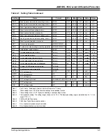
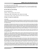
Out of Step Trip Override Timer (OSOT)
This timer is started once an out of step condition is identified (output of OST1). A trip signal is generated if OSOT
times out and the apparent impedance seen by the relay is inside Zone 2 or Zone 3 reach and inside the RT blinder.
The recommended setting is 100 cycles.
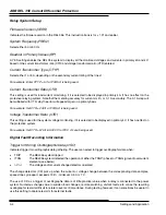
Remote Setting and Time Settings
Remote Setting (SETR)
Set SETR = YES if remote setting via RCP is allowed.
Time Settings (TIME, YEAR, MONTH, DAY, WDAY, HOUR, MIN)
To set the clock in the relay, set TIME = YES and enter correct values as appropriate.
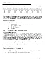
Settings for Tapped Load Applications
Introduction
The REL 356 relay may be used where the line is protected as a two-terminal line but has a load tap in the zone of
protection. In order to apply and set the relay properly in this environment, there must be a transformer at the load tap.
If a transformer is not present, the relays can not be set to limit the zone of protection, and the power line must be treated
as a three-terminal line.
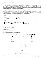
An example of a load tapped two-terminal line is shown in Figure 3-2. Careful consideration must be given to the settings
that are applied to the relay to assure that all faults, up to and into the transformer, are recognized and all faults beyond
the transformer are ignored. In Figure 3-2, a delta-wye transformer is shown with the wye on the load side and with a
grounded neutral. This is the most common application. The ZT in Figure 3-2 is the transformer impedance, and Z is the
total equivalent impedance looking back into the system from the high voltage terminals of the transformer. What must
be considered are the relay energy levels for faults on the line side of the transformer vs. that for faults on the load side.
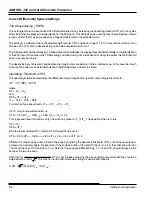
The relay energy is affected by two things; the sequence network settings and the type of fault. The internal faults that
produce the lowest network filter output current and the external faults which produces the highest filter output current
must regulate the settings.
If the relay is set to have a negative sequence response, the type of internal phase fault that will produce the lowest
sequence network current will be a CA or AB fault. This minimum internal fault is assumed to occur at the transformer
high terminals (F1). If the relay is set to have no negative sequence response (C2 = 0), then all combinations of phase-
to-phase faults produce a low energy level in the relay. For this phase-to-phase fault, the positive sequence portion of
the current is all that will affect the filter output response, and that current level is equal to V
LN
(2R
C
) where V
LN
is the line
to neutral voltage and R
C
is the current transformer ratio.
The type of external faults that produce the highest sequence network output for faults on the load side of the trans-
former must be considered. Ground faults do not produce any zero sequence current in the relays because of the
presence of the transformer delta, and therefore, only the positive and negative sequence response need to be consid-
ered. If the relay is set for no negative sequence response, it is clearly seen that a three-phase fault on the load side will
produce the highest network current output at the relay location. The fault current, in this case, will be V
LN
/[(Z+ZT)R
C
].
The case where the relay is set to have a negative sequence response (C2
¹
0), presents a more difficult analysis. Due
to the fact that the positive sequence constant (C1) is opposite in sign to the negative sequence constant (C2), and
considering the fact that the high side positive sequence current will lead the low side current by 30 degrees, and the
high side negative sequence current will lag the low side current by 30 degrees for a standard transformer, it can be
Содержание REL 356
Страница 23: ...ABB REL 356 Current Differential Protection 1 10 Product Overview and Specifications ...
Страница 83: ...ABB REL 356 Current Differential Protection 3 36 Settings and Application ...
Страница 127: ...ABB REL 356 Current Differential Protection 5 28 Testing ...
Страница 186: ...LINE SECTIONALIZING USING A PLC AND ABB PROTECTIVE RELAY Page 49 of 53 ...
Страница 187: ...LINE SECTIONALIZING USING A PLC AND ABB PROTECTIVE RELAY Page 50 of 53 ...
Страница 188: ...LINE SECTIONALIZING USING A PLC AND ABB PROTECTIVE RELAY Page 51 of 53 ...
Страница 189: ...LINE SECTIONALIZING USING A PLC AND ABB PROTECTIVE RELAY Page 52 of 53 ...

