LINE SECTIONALIZING USING A PLC AND ABB PROTECTIVE RELAY
Page 20 of 53
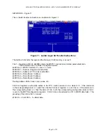
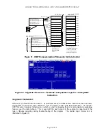
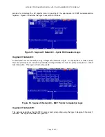
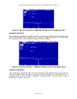
Figure 33. Segment 3 Network 4 – XMIT Instruction and Good Transaction Count
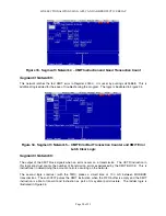
Segment 3 Network 5:
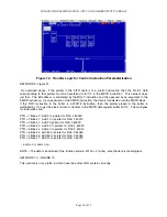
This network latches the last XMIT error in Register 40300. It is reset by pulsing coil 00888. This is
additional logic added for the ease of troubleshooting the program. The logic is illustrated in Figure 34.
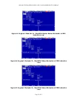
Figure 34. Segment 3 Network 5 – XMIT Error Bad Transaction Counter and XMIT Error
Latch Clear Logic
Segment 3 Network 6:
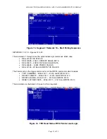
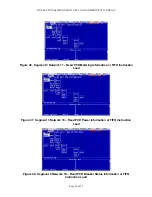
The output of the XMIT block signals when an error occurs on a transmission. The UCTR instruction in
this logic construct counts the number of transmission errors experienced by the XMIT BLOCK. This is
instructional in determining the amount of errors occurring on the network.
The second logic construct (with the TMR) places a dwell time of 100 mS between MODBUS
transmissions. The coil 00307 pulses the XMIT instruction when the FIFO buffer is empty and the XMIT
instruction is able to transmit and instruction as part of its cyclical poll structure. The ladder logic is
illustrated in Figure 35.
Содержание REL 356
Страница 23: ...ABB REL 356 Current Differential Protection 1 10 Product Overview and Specifications ...
Страница 83: ...ABB REL 356 Current Differential Protection 3 36 Settings and Application ...
Страница 127: ...ABB REL 356 Current Differential Protection 5 28 Testing ...
Страница 186: ...LINE SECTIONALIZING USING A PLC AND ABB PROTECTIVE RELAY Page 49 of 53 ...
Страница 187: ...LINE SECTIONALIZING USING A PLC AND ABB PROTECTIVE RELAY Page 50 of 53 ...
Страница 188: ...LINE SECTIONALIZING USING A PLC AND ABB PROTECTIVE RELAY Page 51 of 53 ...
Страница 189: ...LINE SECTIONALIZING USING A PLC AND ABB PROTECTIVE RELAY Page 52 of 53 ...


