LINE SECTIONALIZING USING A PLC AND ABB PROTECTIVE RELAY
Page 9 of 53
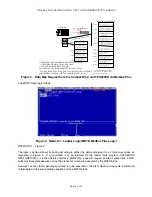
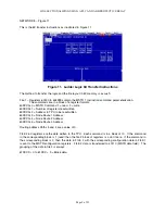
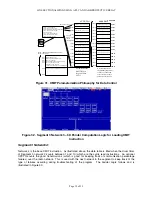
NETWORK 8 – Figure 11
This is the 6X transfer instructions as illustrated in Figure 11
Figure 11. Ladder Logic 6X Transfer Instructions
The method to transfer the logic and the file layout in 6X memory is as such:
File 1 – Registers 60000 to 604999 contain the MSTR 1 instruction command parameterization.
The commands are in a block of 6 register formats.
0 = MSTR Command 1 = read 2 = write
1 = Number of registers read/written
2 = Address in TPU to be read/written
3 = Node Route 1 Address
4 = Node Route 2 Address
5 = Node Route 3 Address
Routing address Paths 5 and 4 are a value of 0.
FILE 2 6X registers are the data written to the TPU. Each command is in a block of 10. If the command
in the corresponding block is 1 (read) then the file 2 block of registers is a don’t care. If the command in
the corresponding block is 2, then the data in FILE 2 with the corresponding configuration data in FILE 1
is sent to the MSTR configuration registers. FILE 2 data is transferred to 40110 (MSTR data field). The
grouping of the data in file 2 is always:
0 to 61XXX + 9 = Block data.
Содержание REL 356
Страница 23: ...ABB REL 356 Current Differential Protection 1 10 Product Overview and Specifications ...
Страница 83: ...ABB REL 356 Current Differential Protection 3 36 Settings and Application ...
Страница 127: ...ABB REL 356 Current Differential Protection 5 28 Testing ...
Страница 186: ...LINE SECTIONALIZING USING A PLC AND ABB PROTECTIVE RELAY Page 49 of 53 ...
Страница 187: ...LINE SECTIONALIZING USING A PLC AND ABB PROTECTIVE RELAY Page 50 of 53 ...
Страница 188: ...LINE SECTIONALIZING USING A PLC AND ABB PROTECTIVE RELAY Page 51 of 53 ...
Страница 189: ...LINE SECTIONALIZING USING A PLC AND ABB PROTECTIVE RELAY Page 52 of 53 ...

