ABB REL 356 Current Differential Protection
2-13
Installation, Operation and Maintenance
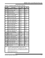
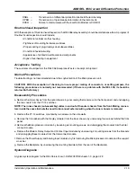
A bit set to “1” signifies that the corresponding failure has been detected. For example, the following failures will result
in a bit pattern:
ROM CHECKSUM
(Bit 2)
Analog Input
(Bit 4)
Processor 1
(Bit 12)
The bit pattern which results is shown below:
Bit Pattern
0 0 0 1
0 0 0 0
0 0 0 1
0 1 0 0
Bit Number
15 14 13 12 11 10 9 8
7 6 5 4
3 2 1 0
Hex “VALUE”
1
0
1
4
Display
For normal error-free system performance, the “VALUE” field display is “0”.
The status display is generated by “OR”ing, the self-test status from Processor 1 and Processor 2. A zero value
indicates that no self-test failure has occurred. A non-zero value in the low byte (bits 0 to 7) represents an REL 356
failure condition which enables the failure alarm, and disables tripping. A non-zero value in the third character from the
right (bits 8 to 11) indicate a self-test- warning which enables the failure alarm, but does not disable tripping. The left-
most character (bits 12 to 15) indicates which processor(s) detected the failure.
Test Enable
A digital fault record is triggered, when the ENTER key is depressed, while the TEST mode TEST function is selected
on the front panel.
Standing Relay Trip
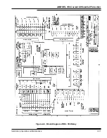
A real-time status monitor of the Standing Relay Trip (SRT) logic signal is provided as a test mode function. The value
of the SRT function is YES if any of the trip relays is enabled, other-wise, the value is “NO”.
CAUTION: The user should verify that SRT = “NO” prior to putting the REL 356 in service after testing.
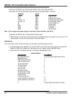
Network Interface
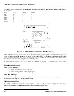
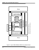
Three options are available for interfacing between REL 356 and a variety of local and remote communication devices.
• RS-232C/PONI - for single point computer communication
• INCOM/PONI - for local network communication
• PONI-M RS485 - for Modbus network communication
An IBM PC or compatible computer, with software provided (WRELCOM), can be used to monitor the settings, 16 fault
data records, 3 oscillographic records, and metering information. For a remote setting, SETR should be set to “YES”;
then the settings can be changed (remotely) with a user-defined password. If a user loses his assigned password, a new
password can be installed by turning the REL 356 relay’s dc power supply “OFF” and then “ON”. REL 356 allows a
change of password within the next 15 minutes, by using a default “PASSWORD”.
Содержание REL 356
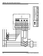
Страница 23: ...ABB REL 356 Current Differential Protection 1 10 Product Overview and Specifications ...
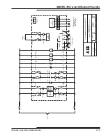
Страница 83: ...ABB REL 356 Current Differential Protection 3 36 Settings and Application ...
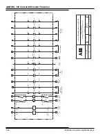
Страница 127: ...ABB REL 356 Current Differential Protection 5 28 Testing ...
Страница 186: ...LINE SECTIONALIZING USING A PLC AND ABB PROTECTIVE RELAY Page 49 of 53 ...
Страница 187: ...LINE SECTIONALIZING USING A PLC AND ABB PROTECTIVE RELAY Page 50 of 53 ...
Страница 188: ...LINE SECTIONALIZING USING A PLC AND ABB PROTECTIVE RELAY Page 51 of 53 ...
Страница 189: ...LINE SECTIONALIZING USING A PLC AND ABB PROTECTIVE RELAY Page 52 of 53 ...

