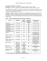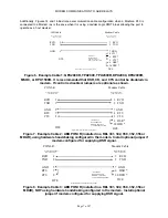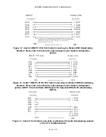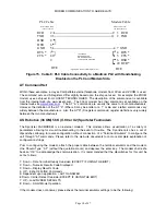
MODEM COMMUNICATION TO ABB RELAYS
Page 11 of 47
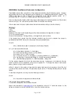
9600 Baud
7 Data Bits
1 Stop
Even Parity
Hardware or No Flow Control depending upon the cable selected and configuration of modem.
VT 100 Terminal Emulation
Inbound Communications: Carriage Return = Carriage Return and Line Feed
If the modem does connect, then the following command may be sent to initialize the modem to
parameterize the RS 232 com ports to the proper mode as explained below.
AT=&F1
&F1 = Initialize the modem to Hardware Control Factory Defaults.
AT = &A3 &B1 &C1 &D0 &G0 &H1 &I0 &K1 &M4 &N0 &P0 &R2 &S0 &T5 &U0 &Y1
&A = Protocol Indicators Added (error control and data compression) (3 = Yes)
&B = Serial Port Rate (0= Follows Connection Rate)
&C = Carrier Detect Override (1 = Overridden)
&D = Data Terminal Ready Control (0= Overridden)
&G= Guard Tone (0 = USA & Canada)
&H = Hardware Flow Control (1 = CTS Enabled, 0 = Disabled)
& I = Software Flow Control (0 = Disabled)
& K = Data Control Compression (Auto Enable Disabled =0)
& M = Error Control (4 = Normal)
& N = Sets Connect Speed (0 = Determined by remote modem).
& P = Rotary Dial Ratio Pulse (0 = USA & Canada)
& R = RD Hardware Flow Control (RTS) (2 = Received Data To Computer)
& S = Data Set Ready Operation (0 = DSR Overridden – Always ON)
& T = Test Loop Enable (5 = Inhibits Test Mode)
& U = Floor Connect Speed (Determined by &N Codes 0 = Best Possible Speed)
& Y = Break Handling (1 = Expedited, Destructive)
For this modem, Register S0 controls the Auto-answer feature. Autoanswer is controlled via the dip-
switch position 5 and a combination of the value in register S0. To change the value of auto answer
pickup (number of rings) send the command:
ATS0= X, where X is the number of rings which the device shall sense for phone pickup. Note if the host
is to dial out the number at all times, this parameter may be set to a “0” thereby disabling the auto answer
feature.
Once the commands are written to the modem, one must write them into the modem’s non-volatile
memory. The command should be sent as follows to the modem:
AT=&W0
Or
AT=&W1
The US ROBOTICS Sportster Modem offers two NVRAM profiles. W0 places the parameters in to Profile
1, whereas W1 places the parameters in Profile 2.
Содержание REL 356
Страница 23: ...ABB REL 356 Current Differential Protection 1 10 Product Overview and Specifications ...
Страница 83: ...ABB REL 356 Current Differential Protection 3 36 Settings and Application ...
Страница 127: ...ABB REL 356 Current Differential Protection 5 28 Testing ...
Страница 186: ...LINE SECTIONALIZING USING A PLC AND ABB PROTECTIVE RELAY Page 49 of 53 ...
Страница 187: ...LINE SECTIONALIZING USING A PLC AND ABB PROTECTIVE RELAY Page 50 of 53 ...
Страница 188: ...LINE SECTIONALIZING USING A PLC AND ABB PROTECTIVE RELAY Page 51 of 53 ...
Страница 189: ...LINE SECTIONALIZING USING A PLC AND ABB PROTECTIVE RELAY Page 52 of 53 ...

