Power Automation and Protection Division
I.L. 40-201.9
REL 352 Version 1.00
4-7
4
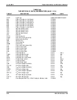
RELAY STATUS
DESCRIPTION
BIT NUMBER
External RAM Failure
0
←
Least Significant
EEPROM Failure
1
Right-Most
ROM Checksum Failure
2
Position
Dual-Port RAM Failure
3
Analog Input Failure
4
Processor Failure
5
±
12V P.S.Fail
6
Modem Failure
7
EEPROM Warning
8
Power Supply 1 Failure
9
Power Supply 2 Failure
10
Dual Port RAM
Com Status Warning
11
Failure Detected by Processor 1
12
Failure Detected by Processor 2
13
0
14
0
15
←
Most Significant
Left-Most
Position
A bit set to “1” signifies that the corresponding failure has been detected. For example, the fol-
lowing failures will result in a bit pattern:
ROM CHECKSUM
(Bit 2)
Analog Input
(Bit 4)
Processor 1
(Bit 12)
The bit pattern which results is shown below:
Bit Pattern
0 0 0 1
0 0 0 0 0 0 0 1
0 1 0 0
Bit Number
15 14 13 12 11 10 9 8 7 6 5 4
3 2 1 0
Hex “VALUE”
1
0
1
4
Display
For normal error-free system performance, the “VALUE” field display is “0”.
The status display is generated by “OR”ing, the self-test status from Processor 1 and Processor
2. A zero value indicates that no self-test failure has occurred. A non-zero value in the low byte
(bits 0 to 7) represents an REL 352 failure condition which enables the failure alarm, and dis-
ables tripping. A non-zero value in the third character from the right (bits 8 to 11) indicate a self-
test-warning, but does not disable tripping. The left-most character (bits 12 to 15) indicates
which processor(s) detected the failure.
Содержание REL 352
Страница 2: ......
Страница 13: ...I L 40 201 9 Power Automation and Protection Division 1 6 REL 352 Version 1 00 Figure 1 1 REL 352 Front Panel ...
Страница 14: ...Power Automation and Protection Division I L 40 201 9 REL 352 Version 1 00 1 7 1 Figure 1 1a REL 352 Rear view ...
Страница 16: ......
Страница 130: ......


