


Power Automation and Protection Division
v
REL 352 Version 1.00
E-1
Microprocessor Module Block Diagram - - - - - - - - - - - - - - - - - - - - - E-3
E-2
REL 352 Processor 1 Memory Map - - - - - - - - - - - - - - - - - - - - - - - E-4
E-3
REL 352 Processor 2 Memory Map - - - - - - - - - - - - - - - - - - - - - - - E-4
E-4
REL 352 Microprocessor Module Component Location Diagram- - - - - - - - - E-5
E-5
REL 352 Microprocessor Module Schematic - - - - - - - - - - - - - - - - - - E-6
E-5
REL 352 Microprocessor Module Schematic - - - - - - - - - - - - - - - - - - E-7
E-5
REL 352 Microprocessor Module Schematic - - - - - - - - - - - - - - - - - - E-8
E-5
REL 352 Microprocessor Module Schematic - - - - - - - - - - - - - - - - - - E-9
E-5
REL 352 Microprocessor Module Schematic - - - - - - - - - - - - - - - - - E-10
E-5
REL 352 Microprocessor Module Schematic - - - - - - - - - - - - - - - - - E-11
E-5
REL 352 Microprocessor Module Schematic - - - - - - - - - - - - - - - - - E-12
F-1
REL 352 Display Module Component Location Diagram- - - - - - - - - - - - - F-2
F-2
REL 352 Display Module Schematic - - - - - - - - - - - - - - - - - - - - - - F-3
G-1
REL 352 Power Supply PC Board - - - - - - - - - - - - - - - - - - - - - - - G-3
G-2
REL 352 Power Supply Schematic (See inside back cover) - - - - - - - - - - - G-4
H-1
REL 352 Analog Input Module Block Diagram- - - - - - - - - - - - - - - - - - H-2
H-2
REL 352 Analog Input Module Component Location Diagram - - - - - - - - - - H-3
H-3
REL 352 Analog Input Module Schematic - - - - - - - - - - - - - - - - - - - - H-4
H-3
REL 352 Analog Input Module Schematic - - - - - - - - - - - - - - - - - - - - H-5
H-3
REL 352 Analog Input Module Schematic - - - - - - - - - - - - - - - - - - - - H-6
H-3
REL 352 Analog Input Module Schematic - - - - - - - - - - - - - - - - - - - - H-7
K-1
REL 352 / TCF-10B Intercorrecting Diagram - - - - - - - - - - - - - - - - - - K-1
K-2
Signal Polarity - - - - - - - - - - - - - - - - - - - - - - - - - - - - - - - - - K-2
K-3
Square Wave Duration 60 Hz - - - - - - - - - - - - - - - - - - - - - - - - - - K-4
K-4
Square Wave Duration 50 Hz - - - - - - - - - - - - - - - - - - - - - - - - - - K-5
L-1
REL 352 Block Diagram - - - - - - - - - - - - - - - - - - - - - - - - - - - - L-2
L-2
REL 352 Logic Diagram (sheet 1 of 3) - - - - - - - - - - - - - - - - - - - - - L-3
L-2
REL 352 Logic Diagram (sheet 2 of 3) - - - - - - - - - - - - - - - - - - - - - L-4
L-2
REL 352 Logic Diagram (sheet 3 of 3) - - - - - - - - - - - - - - - - - - - - - L-5
L-3
REL 352 Backup System Logic Diagram - - - - - - - - - - - - - - - - - - - - L-6
E
F
G
H
K
L
List of Figures
(continued)
Figure No.
Page No.
Содержание REL 352
Страница 2: ......
Страница 13: ...I L 40 201 9 Power Automation and Protection Division 1 6 REL 352 Version 1 00 Figure 1 1 REL 352 Front Panel ...
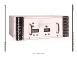
Страница 14: ...Power Automation and Protection Division I L 40 201 9 REL 352 Version 1 00 1 7 1 Figure 1 1a REL 352 Rear view ...
Страница 16: ......
Страница 130: ......


