I.L. 40-201.9
Power Automation and Protection Division
4-2
REL 352 Version 1.00
Analog input circuitry consists of three (3) current transformers (I
A
, I
B
, I
C
) three (3) voltage
transformers, (V
A
, V
B
and V
C
), and low-pass filters. The six transformers are located on the
Backplane PC Board (
see Appendix A
). The primary winding of all six transformers are directly-
connected to the input terminal TB6/1 thru 12 (
see Functional Block Diagram, Appendix N, Figure N-
1
); the secondary windings are connected thru the Interconnect module to the Analog Input
module.
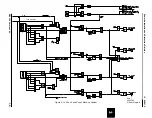
As shown in Figure 4-1, dry contact outputs for breaker failure initiation (BFI), reclosing initiation
(RI), reclosing block (RB), failure alarm and trip alarm are located on the Backplane PC Board.
As shown in Figure 4-2, the power system ac quantities (V
a
, V
b
, V
c
, V
n
, I
a
, I
b
, I
c
), as well as the
dc sources are connected to the left side 1FT-14 switch (front view). All the trip contact outputs
are connected to the right-side 2 FT-14 switch (front view). Switches 13 and 14 on 2 FT-14 may
be used for disabling the Breaker Failure Initiation/Reclosing Initiation (BFI/RI) control logic.
(
See also external connections, Block Diagram, Appendix N, Figure N-1.
)
The INCOM/PONI communication box is mounted thru the Backplate of the outer chassis and
connected to the Backplane module. An RS-232C serial port is provided for remote transmis-
sion of target data. The serial port is also available for networking, data communications, and
remote settings (
see section 4.7, NETWORK INTERFACE
).
3.
REL 352 FRONT PANEL DISPLAY
The front panel display consists of a vacuum fluorescent display set of seven LED indicators,
seven key switches (
as shown in Figure 1-1
).
3.1.
Vacuum Fluorescent Display
The vacuum fluorescent display (blue color) contains four alphanumeric characters for both the
function field and the value field. All the letters or numbers are fourteen segment form (7.88 mm
x 13 mm in size). The display is blocked momentarily every minute for the purpose of self-
check; this will not affect the relay protection function.
A “DISPLAY SAVER” feature turns-off the display if no key activity for 3 minutes is detected.
3.2.
Indicators
There are 7 LED indicators on the front panel display:
• 1 “relay-in-service” indicator
• 1 “value accepted” indicator
• 5 display-select indicators
When the “Relay-in-Service” LED illuminates, the REL 352 relay is in service, there is dc power
to the relay and the relay has passed the self-check and self-test. The LED is turned “OFF” if
the relay-in-service relay has at least one of the internal failures shown in the “Test” mode.
The “Value Accepted” LED flashes only once, to indicate that a value has been entered suc-
cessfully.
The 5 indicators used for the display selection are:
• Settings
• Volts/Amps/Angle
• LAST FAULT
• PREVIOUS FAULT
• Test
One of these indicators is always illuminated, indicating the mode selected.
Содержание REL 352
Страница 2: ......
Страница 13: ...I L 40 201 9 Power Automation and Protection Division 1 6 REL 352 Version 1 00 Figure 1 1 REL 352 Front Panel ...
Страница 14: ...Power Automation and Protection Division I L 40 201 9 REL 352 Version 1 00 1 7 1 Figure 1 1a REL 352 Rear view ...
Страница 16: ......
Страница 130: ......


