Power Automation and Protection Division
I.L. 40-201.9
REL 352 Version 1.00
B-1
B
A
P
P
E
N
D
I
X
INTERCONNECT MODULE
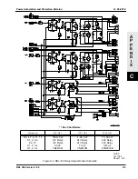
Schematic - - - - - - - - - - - - - - 1618C35
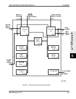
Component Location Diagram - - - - 1618C45
The Interconnect module (see Figure B-1 and Schematic) becomes the floor of the inner chassis and provides
electrical connectors for all other modules; it connects from the Backplane module (at the rear), to the Analog
Input and Power Supply modules (at the left and right sides, respectively), to the Relay Output and Contact Input
modules, in the center, and to the Microprocessor and Display modules at the front of the chassis. The compo-
nents on the Interconnect module include:
• Optoisolated Transistor Output for Communication Transmitter Keying
Selection for transmitter keying is provided by JMP7:
Position
Voltage
1-2
125 Vdc
3-4
48 Vdc
5-6
15/20 Vdc
Factory setting is 5-6 (15/20 Vdc)
• Communication Receiver Interface Between Optoisolated Inputs on the Contact
Input Module and the Microprocessor Module
• Channel alarm relay
This interface also includes signal polarity inversion controlled by jumpers.
The Jumper assignments are:
JMP1
Channel Fail
JMP2
MARK 2
JMP3
SPACE 2
JMP4
MARK 1
JMP5
SPACE 1
JMP6
KEY OUT
Related connections are shown below:
Module
Connector
Destination
J11, J12, J13
Backplane
J7
Power Supply
J9
Analog Input
J5
Microprocessor
JB1
Relay Output (Single Pole Trip)
JB2
Relay Output (Base 1)
JB3
Relay Output (Base 2)
JB4
Contact Input
Position 1-2 Inverted
(Factory setting)
Position 2-3 normal
Содержание REL 352
Страница 2: ......
Страница 13: ...I L 40 201 9 Power Automation and Protection Division 1 6 REL 352 Version 1 00 Figure 1 1 REL 352 Front Panel ...
Страница 14: ...Power Automation and Protection Division I L 40 201 9 REL 352 Version 1 00 1 7 1 Figure 1 1a REL 352 Rear view ...
Страница 16: ......
Страница 130: ......


