Power Automation and Protection Division
I.L. 40-201.9
REL 352 Version 1.00
4-9
4
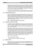
4.4.5. Standing Relay Trip
A real-time status monitor of the Standing Relay Trip (SRT) logic signal is provided as a test
mode function. The value of the SRT function is YES if any of the trip relays is enabled, other-
wise, the value is “NO”.
!
CAUTION
The user should verify that SRT = “NO” prior to putting the REL 352 in service
after testing.
5.
JUMPER CONTROL
The following jumpers are set at the factory; the customer normally does not need to move the
jumpers.
5.1.
Backplane Module
An external jumper is permanently-wired to terminals 13/14 of switch 2FT-14.
When switch 2FT-14/13 or 2FT-14/14 is opened, the BFI and RI output relays are deenergized
to prevent BFI and RI contact closures during system function test.
5.2.
Contact Input Module
The factory sets jumpers (JMP1 thru JMP6) for 15/20 Vdc input source and jumpers (JMP7 thru
JMP9) for 48/125 Vdc input source.
!
CAUTION
If the customer intends to use a voltage other than those specified above, see
Contact Input Module Schematic, Appendix D.
6.
NETWORK INTERFACE
Two options are available for interfacing between REL 352 and a variety of local and remote
communication devices.
• RS-232C/PONI - for single point computer communication
• INCOM/PONI - for local network communication
An IBM PC or compatible computer, with software provided (WRELCOM), can be used to mon-
itor the settings, 16 fault data records, 3 oscillographic records, and metering information. For
a remote setting, SETR should be set to “YES”; then the settings can be changed (remotely)
with a user-defined password. If a user loses his assigned password, a new password can be
installed by turning the REL 352 relay’s dc power supply “OFF” and then “ON”. REL 352 allows
a change of password within the next 15 minutes, by using a default “PASSWORD”.
When in the remote mode, the computer can disable the local setting by showing SET = REM
(in the Metering mode). Then, the setting cannot be changed locally. In this situation, the only
Содержание REL 352
Страница 2: ......
Страница 13: ...I L 40 201 9 Power Automation and Protection Division 1 6 REL 352 Version 1 00 Figure 1 1 REL 352 Front Panel ...
Страница 14: ...Power Automation and Protection Division I L 40 201 9 REL 352 Version 1 00 1 7 1 Figure 1 1a REL 352 Rear view ...
Страница 16: ......
Страница 130: ......


