


I.L. 40-201.9
Power Automation and Protection Division
4-6
REL 352 Version 1.00
Table 4-2:
Binary-to-Hexadecimal Conversion
BIT NUMBER
3/7
2/6
1/5
0/4
HEX DIGIT
0
0
0
0
0
0
0
0
1
1
0
0
1
0
2
0
0
1
1
3
0
1
0
0
4
0
1
0
1
5
0
1
1
0
6
0
1
1
1
7
1
0
0
0
8
1
0
0
1
9
1
0
1
0
A
1
0
1
1
B
1
1
0
0
C
1
1
0
1
D
1
1
1
0
E
1
1
1
1
F
4.4.1.1
Relay Output Test
All relay outputs can be tested using the procedure
described below:
(1) Open the FT switch, using the red handles of
the breaker trip circuits, making sure that the
following jumper is not disturbed:
BFI/RECLOSE ENABLE
(2) Install jumper JMI in position 1-2 on the Micro-
processor module.
(3) Continually depress the “DISPLAY” key until
the “TEST” LED is illuminated; then depress
the “FUNCTION RAISE” or “FUNCTION LOW-
ER” key until the words “TRIP” and “RELY”
appear in the FUNCTION and VALUE fields,
respectively.
(4) Activate the “ENTER” key for the desired dura-
tion of the output relays operation.
(5) Depress the “FUNCTION RAISE” key to select
the following parameters, as desired:
FUNCTION
VALUE
FIELD
FIELD
DESCRIPTION
TRIP
RELY
TRIP (A, B, C)
BFI
RELY
Breaker Failure Initiate
SRI (RI1-1,2)
RELY
Reclose Initiate
3RI (RI2-1,2)
RELY
Reclose Initiate
RB
RELY
Recloser Blocking
GS
RELY
General Start
FALM
RELY
Failure Alarm
TALM
RELY
Trip Alarm
CALM
RELY
Channel Alarm
NOTE:
Activate the “ENTER” key to operate selected output relays.
(6) After completion of this test, restore the system to its operating state by moving JM1 to po-
sition 2-3 on the Microprocessor module, and closing the FT switch red handles.
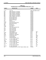
4.4.2. Self Check
The results of the system self-check routines are accessible using the following procedure:
a. Continually depress the “DISPLAY” key until the “TEST” LED is illuminated; then depress
the “FUNCTION RAISE” or “FUNCTION LOWER” key until the word “STAT” appears in the
FUNCTION FIELD.
b. The VALUE FIELD will display the status of the relay in hexadecimal Format:
Содержание REL 352
Страница 2: ......
Страница 13: ...I L 40 201 9 Power Automation and Protection Division 1 6 REL 352 Version 1 00 Figure 1 1 REL 352 Front Panel ...
Страница 14: ...Power Automation and Protection Division I L 40 201 9 REL 352 Version 1 00 1 7 1 Figure 1 1a REL 352 Rear view ...
Страница 16: ......
Страница 130: ......


