Power Automation and Protection Division
I.L. 40-201.9
REL 352 Version 1.00
3-3
3
The IKEY signal is generated in the remote terminal and transmitted over the communications
channel (for example, power line carrier) and received in the local terminal as MARK and
SPACE signals subjected to communication propagation delay (CPD).
The local terminal provides compensation for CPD by delaying local quantities LP and LN using
settings LDT1 and LDT2 (for 3-terminal applications) as shown in Figure 3-6.
The MARK signal and the LP signal are ANDed and a “positive trip coincidence” condition is
generated. The same is true with the SPACE and LN signals. The two are ANDed together and
a “negative trip coincidence” condition is asserted. The composite COUT signal is generated
as shown in figure 3-6. The duration of COUT pulses indicate an internal fault.
External Fault and Load Condition
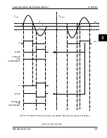
For an external fault (and load condition), the signal relationship is shown in Figure 3-5. Due to
the current directions at both ends, the currents into the relaying units in the local and remote
sites will be 180˚ out of phase. When ANDing the MARK and LP and the SPACE and LN sig-
nals, the outputs of the “positive trip coincidence” and “negative trip coincidence” conditions will
be zero all the time. Therefore, the COUT output will be constant logic “0”.
4.
ON-OFF POWER LINE CARRIER APPLICATIONS
As seen on Figures 3-4, 3-5 and 3-6 the negative half-cycle comparisons only are performed
(setting COMM=2).
ON-OFF PLC operates in the “quiescent” mode, i.e., during normal load state of the transmis-
sion line the carrier is turned “off”, this corresponds to the SPACE condition asserted to contin-
uous “1” state at the receiver. Therefore to block tripping on external faults the carrier must be
turned “on” (“0” state at the receiver).
The ON-OFF PLC applications are referred to as “blocking” systems.
Internal Fault
For internal fault the SPACE and LN signals produce positive coincidence COUT as shown on
Figure 3-4. The pilot trip PLT is enabled by FD2 (fault detector) as illustrated in Figure 3-7.
External Fault
The external fault is illustrated in Figure 3-5; remember that only negative half-cycle compari-
sons are performed. The LN and SPACE comparison results in deasserted COUT (“0” state)
and a pilot trip is blocked.
5.
THREE TERMINAL APPLICATIONS
If the system is used for a three terminal application, there will be two sets of MARK and SPACE
signals received from the remote locations. As illustrated in Figure 3-6, the M1 and S1 (from
remote terminal 1) and M2 and S2 (from remote terminal 2) are compared to the respective
LP1, LN1, LP2 and LN2 signals delayed by the respective LDT1 or LDT2 settings. It is extreme-
ly important that the settings reflect the true channel delays of the communications channel.
The correct comparison of phases is totally dependent on the proper channel delay measure-
ment.
Содержание REL 352
Страница 2: ......
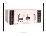
Страница 13: ...I L 40 201 9 Power Automation and Protection Division 1 6 REL 352 Version 1 00 Figure 1 1 REL 352 Front Panel ...
Страница 14: ...Power Automation and Protection Division I L 40 201 9 REL 352 Version 1 00 1 7 1 Figure 1 1a REL 352 Rear view ...
Страница 16: ......
Страница 130: ......

